Drill chuck

A technology of drill chuck and chuck, which is applied in the direction of chuck, drilling tool accessories, drilling/drilling equipment, etc., which can solve the problems affecting the stability, load capacity and durability of the chuck body, and achieve the improvement of radial runout characteristics, the effect of simplifying the manufacturing process

Inactive Publication Date: 2014-06-18
ROHM CO LTD
View PDF7 Cites 1 Cited by
  • Summary
  • Abstract
  • Description
  • Claims
  • Application Information

AI Technical Summary

Problems solved by technology

However, in the cast chuck body according to document EP 0 895 824 A1 the problem arises that stresses are generated when the chuck body hardens, which adversely affects the stability, load capacity and durability of the chuck body

Method used


Image

  • Drill chuck
  • Drill chuck
  • Drill chuck

Examples


Embodiment Construction

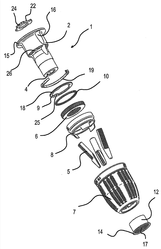
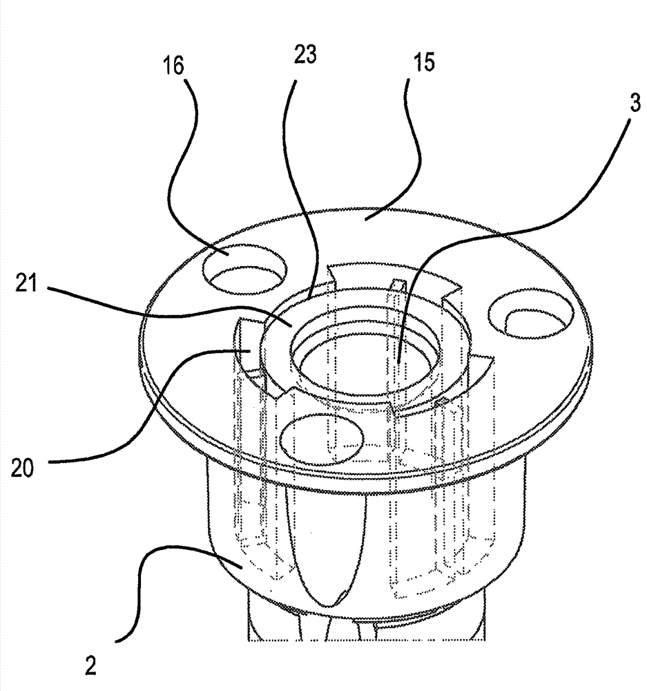
[0050] figure 1 A sectional view of an exemplary embodiment of a drill chuck 1 according to the invention with a chuck body 2 made of fiber-reinforced plastic is shown. The chuck body 2 has a spindle receptacle 3 for receiving a drilling spindle of a drilling machine and, opposite thereto, a tool receptacle 4 . Guided in the chuck body 2 is a caliper 5 , which can be adjusted obliquely to the chuck axis in a guide receptacle in a known manner via a threaded ring 6 . For adjusting the threaded ring 6 , a clamping sleeve 7 is provided, which engages the threaded ring 6 via an intermediate sleeve 8 in the exemplary embodiment shown, but can also bear directly against it. In this case, the threaded ring 6 is supported on the chuck body 2 via the pressure ring 9 and by means of the ball bearing 10 axially rearward in the direction of the spindle receptacle 3 . The threaded ring 6 is supported in the direction of the tool receptacle 4 via a collar-shaped support element 27 which i...


PUM


Abstract

The invention relates to a drill chuck. The drill chuck has a chuck body centered on an axis, made of plastic, and formed with an axially rearwardly open drive-spindle seat, at least one axially extending slot of ring-segment section opening radially inward into the seat, an axially forwardly open tool-holding cavity, and a plurality of angled jaw guides. Respective jaws are movable in the guides and engaged by a threaded ring axially fixed on the body and rotatable about the axis thereon. A tightening sleeve rotatable about the axis on the body is connected to the ring for rotating same.

Description

technical field [0001] The invention relates to a drill chuck with a chuck body made of plastic, in particular fiber-reinforced plastic, with a spindle receptacle and a tool receptacle, in which a drill is guided by means of a threaded ring Adjustable calipers (Spannbacke); and clamping sleeves (Spannhuelse) with adjusting threaded rings. Background technique [0002] Such a drill chuck is known, for example, from EP 0 895 824 A1. Therein, a drill chuck is shown, which has a cast chuck body, which has associated gripping surfaces on its end with the spindle receptacle. However, in the case of cast chuck bodies according to EP 0 895 824 A1 the problem arises that stresses develop during hardening of the chuck body, which adversely affects the stability, load carrying capacity and durability of the chuck body. Contents of the invention [0003] The present invention aims at alleviating the above-mentioned disadvantages. [0004] This object is achieved according to the in...

Claims


Application Information

Patent Timeline
Patent Type & Authority Applications(China)
IPC IPC(8): B23B31/12
CPCB23B31/1238B23B2226/61B23B2231/38B23B2231/44Y10S279/902Y10T279/17623Y10T279/17632Y10T279/32
Inventor P.申克
Owner ROHM CO LTD
Why Eureka
Try Eureka