Axial turbine

An axial-flow turbine, turbine technology, applied in the direction of impact engine, reaction engine, non-variable-capacity engine, etc., can solve the efficiency of the damage distance of the wing plate, the site conditions that cannot be selected, and the angle of the turbine wing plate. Efficiency maximization and other issues, to achieve the effect of large distance efficiency

Active Publication Date: 2014-06-11
崔爀善
View PDF4 Cites 3 Cited by
  • Summary
  • Abstract
  • Description
  • Claims
  • Application Information

AI Technical Summary

Problems solved by technology

That is, since the turbines do not include submerged turbines and collision turbines, they cannot be selectively used for the corresponding site conditions
Further, the angel efficiency of the turbine airfoil cannot be maximized according to related art techniques
In addition, this technique does not prevent the loss of flow rate
Furthermore, in the technology according to the related art, since the pressure of the fluid pushes the flap down, the flap is damaged and distance efficiency cannot be maximized
In addition, the problem of fluid temperature drop cannot be solved according to the technology of the related art
Finally, the problem of pressure applied to loads on the flaps has not been solved according to the techniques of the related art

Method used


Image

  • Axial turbine
  • Axial turbine
  • Axial turbine

Examples


Embodiment Construction

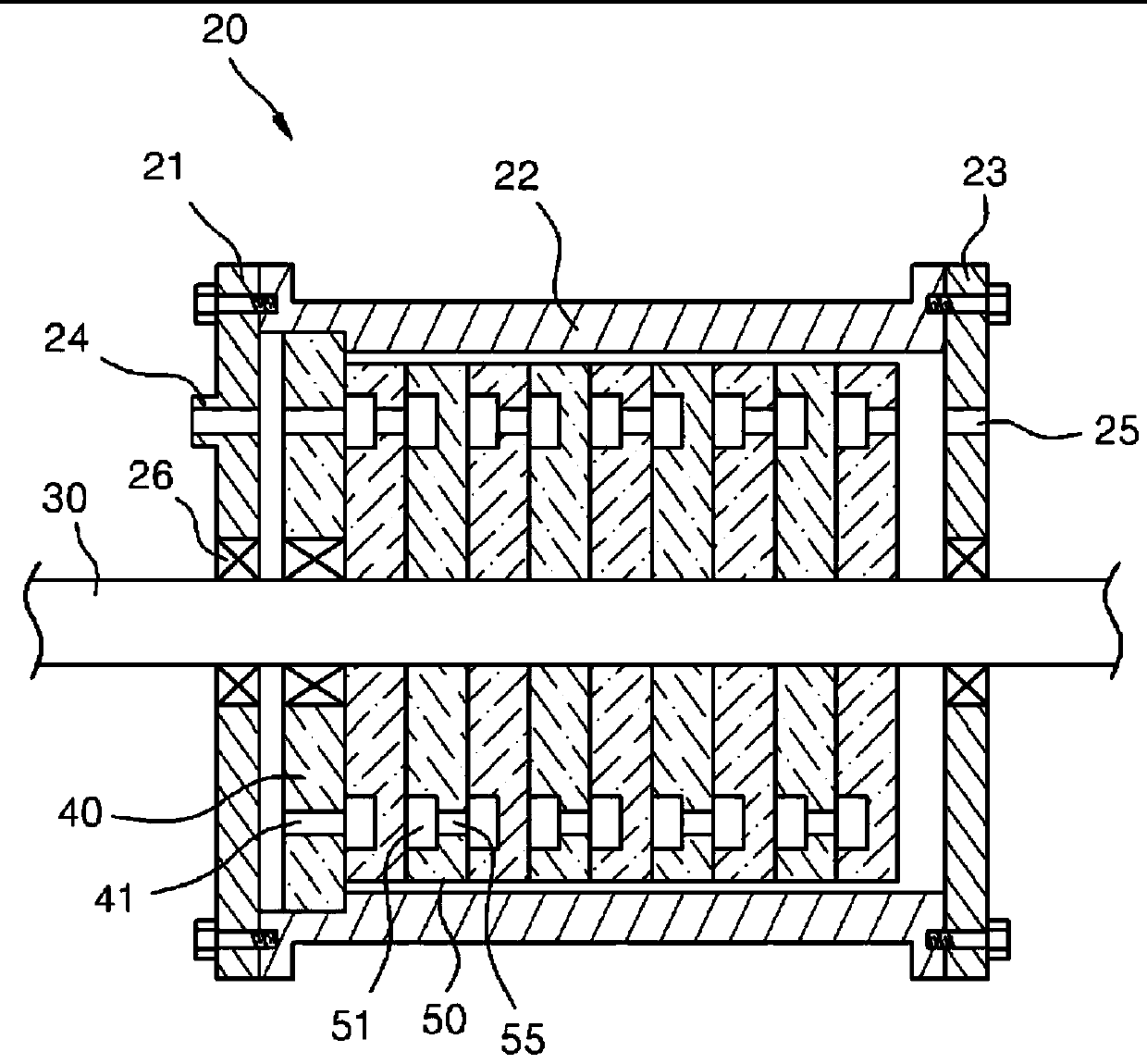
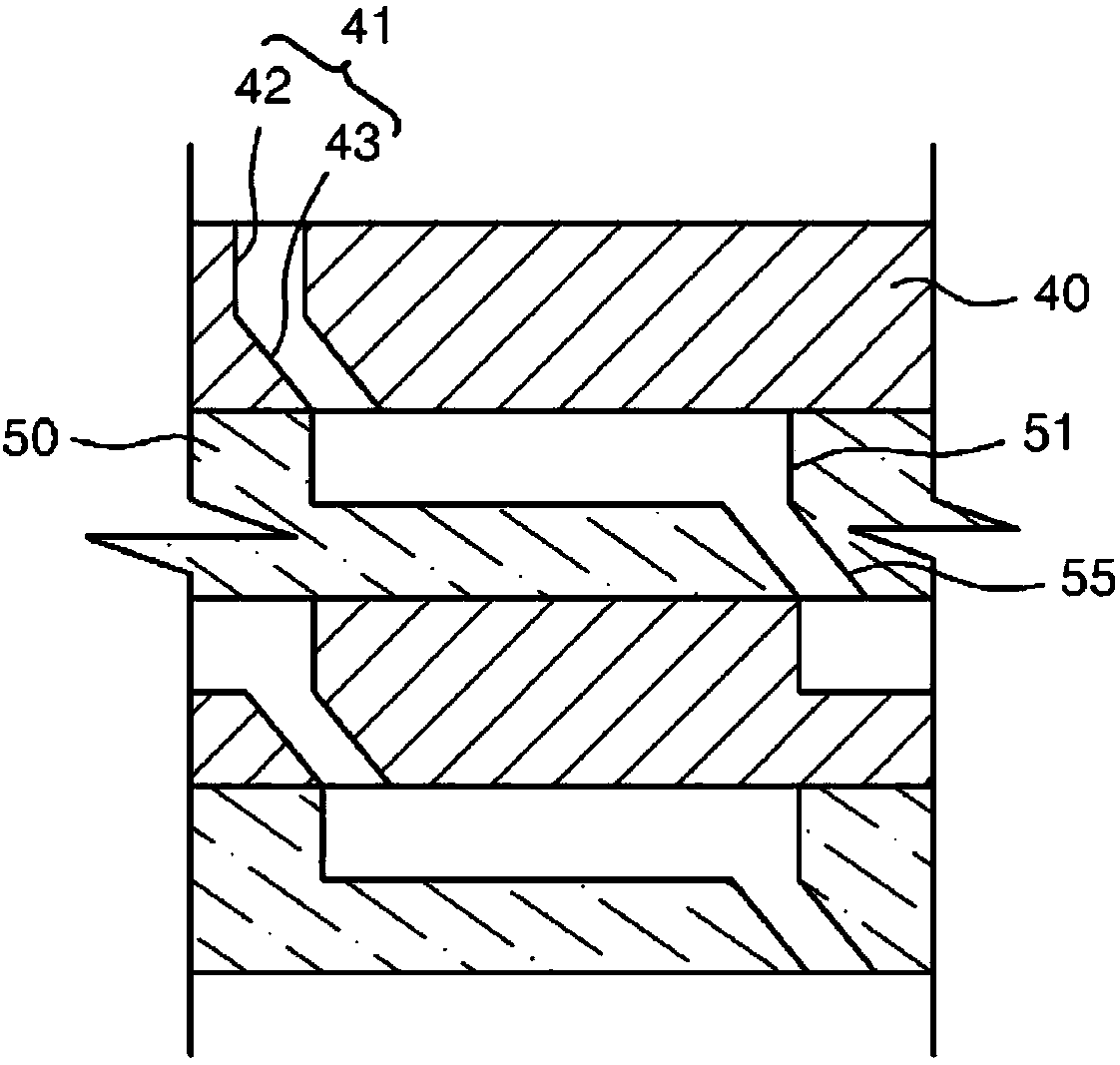
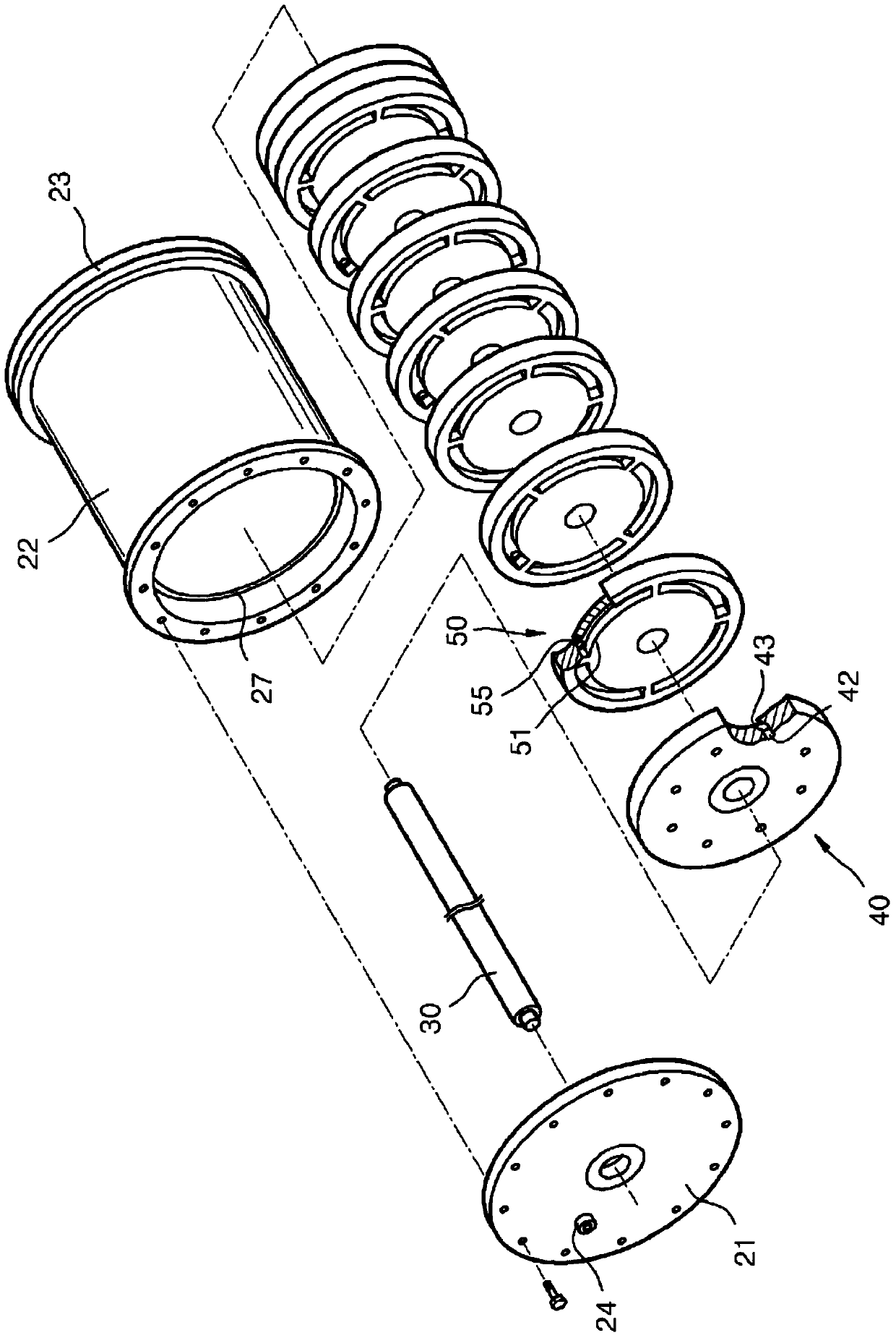
[0064] The improved structure applied to the axial flow turbine of the present invention is as Figure 2 to Figure 23 shown.

[0065] In describing the present invention, when a detailed description of related known functions and structures would unnecessarily obscure the essence of the present invention, the detailed description will be omitted.

[0066] In addition, the following terms are set in consideration of their functions in the present invention and may be different from the manufacturer's intention and custom, and their definitions should be based on the contents of the entire specification.

[0067] First, the invention relates to axial flow turbines and includes a fluid filled submerged turbine 100 . The turbine includes: a main body 110 having a space 111, an inlet 112 and an outlet 113, the interior of the space 111 is filled with fluid, and the inlet 112 and the outlet 113 are respectively located on one side and the opposite side of the main body; a rotating ...


PUM


Abstract

The present invention relates to an improved structure for an axial turbine. To this end, the present invention is provided with a submerged turbine (100) in which a liquid is filled. Also, the present invention is provided with an impulse turbine (200) which spouts high-pressure liquid to rotate blades. The above structure of the present invention has the advantage of being able to selectively use the structure of the turbine to suit the given circumstances when configuring and using a submerged-type turbine, an impulse-type turbine or a hybrid-type turbine (i.e. a combined submerged and impulse turbine). Accordingly, product quality and reliability can be significantly improved, thereby providing satisfaction to the operator.

Description

technical field [0001] The present invention relates to an improved structure of an axial flow turbine which can be arbitrarily formed into a single stage or a multistage according to the type, flow velocity or head of the fluid, and more particularly, to a submerged turbine ( submerged turbine), collision turbine (colliding turbine), repulsive turbine (repulsive turbine) or combined turbine (combined turbine), wherein the composite turbine is combined by two of underwater turbine, collision turbine and repulsive turbine to Selectively used, through such a combination, can significantly improve the quality and reliability of the product to satisfy the operator. [0002] Scope of application: gas, steam, hydraulic, wind, tidal flow, tidal energy, various power engines Background technique [0003] The present invention is an improvement of Korean patent application with publication number 2010-0105103 (Korean patent application with application number 2009-0023951 titled axi...

Claims


Application Information

Patent Timeline
Patent Type & Authority Applications(China)
IPC IPC(8): F01D1/10F01D5/14
CPCF01D1/026Y02E10/223F03B3/04F03B1/00Y02E10/20
Inventor 磪焃善
Owner 崔爀善
Why Eureka
Try Eureka