An mri B0 field compensation amplifier based on pid regulation and pwm technology

An amplifier and amplifying board technology, applied in power amplifiers, improving amplifiers to improve efficiency, negative feedback circuit layout, etc., can solve problems such as difficult to apply, large B0 field compensation coil inductance, self-excited oscillation, etc., to solve the problem of efficiency Low, wide load matching effect

Active Publication Date: 2016-09-28
XBO MEDICAL SYST
View PDF3 Cites 0 Cited by
  • Summary
  • Abstract
  • Description
  • Claims
  • Application Information

AI Technical Summary

Problems solved by technology

Although power amplifiers are widely used in the market, they are difficult to be used in B0 field compensation in magnetic resonance imaging systems.
The inductance of the B0 field compensation coil of the magnetic resonance imaging system is relatively large, and different coils have certain differences, so it is difficult for a general amplifier to adapt to its load range, resulting in self-excited oscillation, resulting in damage to the amplifier

Method used


Image

  • An mri B0 field compensation amplifier based on pid regulation and pwm technology

Examples


Embodiment

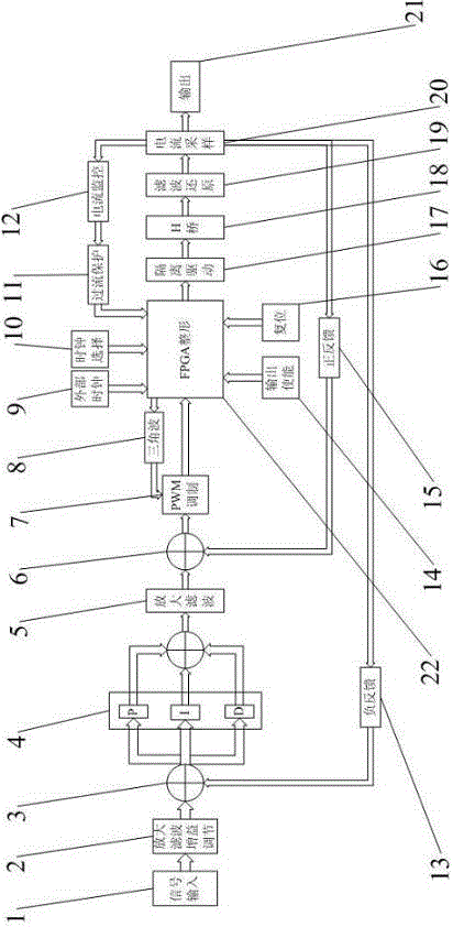
[0016] The structure of the present invention will be described in detail below through embodiments and in conjunction with the accompanying drawings.

[0017] As shown in accompanying drawing 1, the present invention at least includes: amplification filter gain adjustment module 2, PID adjustment module 4, adder module 3,6, PWM modulation module 7, triangular wave generation circuit module 8, FPGA shaping module 22, isolation drive module 17. Signal amplification module (i.e. H-bridge module) 18. Filter restoration circuit module 19. Current sampling module 20. Current monitoring module 12. Overcurrent protection module 11. External clock input interface 9. Clock selection interface 10. Output enabling module 14. Reset interface 16, positive feedback module 15, and negative feedback module 13.

[0018] The input signal enters from the signal input interface 1 of the compensation amplifier board, and enters the adder module 3 through the amplification filter gain adjustment ci...


PUM


Abstract

The invention relates to an MRI (Magnetic Resonance Imaging) B0 cancellation amplifier based on a PID (Proportion Integration Differentiation) regulation technology and a PWM (Pulse-Width Modulation) technology. The MRI B0 compensation amplifier comprises a positive-negative power supply module and a compensation amplifying circuit board, and technical measures such as amplified filtration, negative feedback, PID frequency response regulation, positive feedback, PWM, PWM waveform shaping based on an FPGA (Field Programmable Gate Array), an isolation driving technology, signal multiplication, signal filtration and reduction, electric current sampling, electric current monitoring and over-current protection are adopted. The MRI B0 compensation amplifier has the following advantages that: feedback gain demands are proper, so that the system operation is more stable; by virtue of PID regulation, the load matching range of the compensation amplifier is wider; the defects that small matching range and self excitation occurring in an unmatched load range of a common amplifier are solved; the response output speed can be quickened to a certain extent, so that over-slow response speed caused by over-high load sensibility can be avoided; a PMW switching mode is adopted, the efficiency of the compensation amplifier can be up to 90%, and the defect of low efficiency of the common amplifier is solved.

Description

technical field [0001] The invention relates to an MRI B0 field compensation amplifier based on PID regulation and PWM technology, belonging to the technical field of power amplifiers in medical equipment. Background technique [0002] The power amplifier is a device that amplifies the input reference signal into the required signal. The required signal can be a current signal or a voltage signal. There are two basic requirements for the power amplifier: one is that the change of the output signal can be consistent with the change of the input preference ; Second, the loss of the entire power amplifier is low. [0003] Power amplifiers are generally divided into Class A, Class B, Class AB and Class D amplifiers. Class AB is widely used in the audio field with less distortion, while Class D is widely used in industrial control fields such as portable audio equipment and motors because of its high efficiency. be widely used. Due to the existence of B0 eddy current in the mag...

Claims


Application Information

Patent Timeline
Patent Type & Authority Patents(China)
IPC IPC(8): H03F1/02H03F1/34H03F3/20
Inventor 董聪坤王作辉王小辉刘培植刘景顺
Owner XBO MEDICAL SYST
Why Eureka
Try Eureka