LED display and LED control system
A technology of LED display and display, applied in static indicators, instruments, etc., can solve the problems of large PCB area and low refresh rate
- Summary
- Abstract
- Description
- Claims
- Application Information
AI Technical Summary
Problems solved by technology
Method used
Image
Examples
Embodiment 1
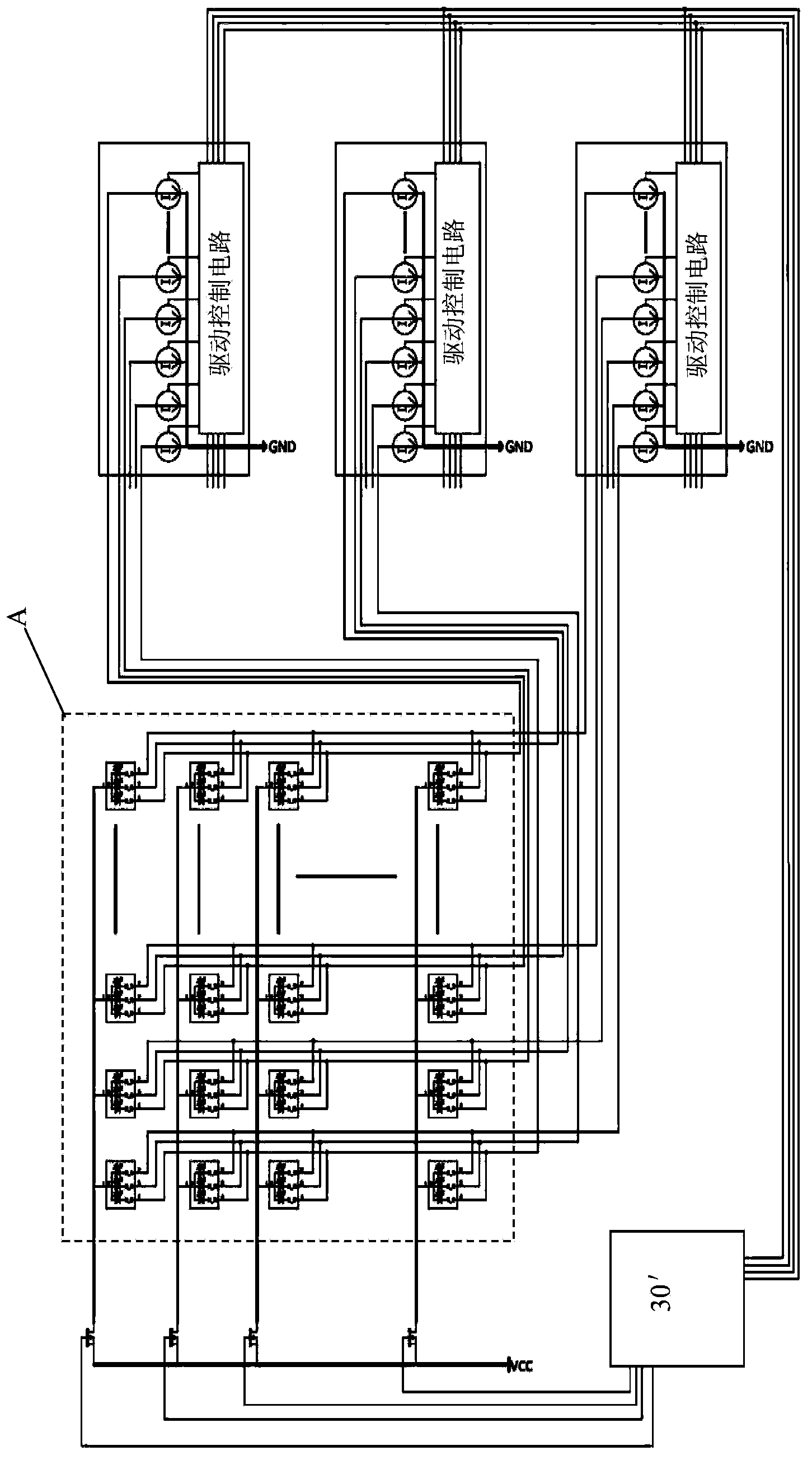
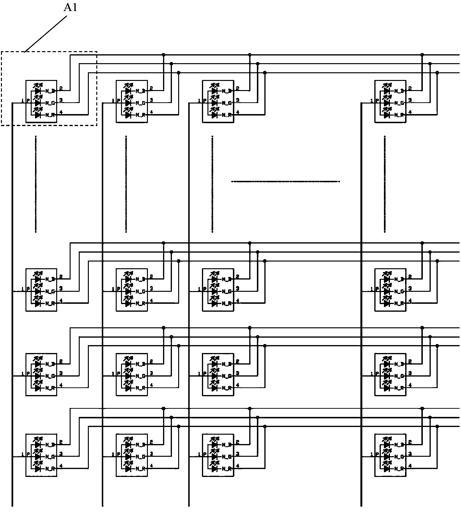
[0077] Figure 4 is a schematic structural view of an LED display according to Embodiment 1 of the present invention; Figures 5a to 5c It is a schematic diagram of the detailed structure of the LED display according to Embodiment 1 of the present invention. Such as Figure 4 , Figure 5a , 5b , 5c, the LED display includes: LED display panel 10; display drive circuit 30, including: switch circuit 31, drive circuit 33 and control circuit 35, wherein the first end of one of switch circuit 31 and drive circuit 33 Connect to the power terminal of the power supply equipment, the first end of the other is connected to the ground terminal of the power supply equipment; the second end of one of the switch circuit 31 and the drive circuit 33 is connected to the anode of the LED display panel 10, and the second end of the other terminal is connected to the cathode of the LED display panel 10; the control circuit 35 includes: a power supply control circuit 351 and a driver 353, wher...
Embodiment 2
[0112] Figures 6a to 6c is a schematic structural diagram of an LED display according to Embodiment 2 of the present invention. Such as Figure 6a As shown, the field effect tube in the LED display can also be an N-MOS tube, and the LED display panel 10 can include LED particles in M rows and N columns, and each LED particle includes a red light tube, a green light tube and a blue light tube respectively. tube, wherein the cathode of the red light tube, the cathode of the green light tube and the cathode of the blue light tube in the i-th LED particle in each row are connected in parallel to the i-th node, each node in each row is connected in parallel, respectively The drain of a corresponding N-MOS tube in the switch circuit 31 is connected; the anodes of the red light tubes of the LED particles in each column are respectively connected in parallel, as a connecting terminal of the anode of the LED display panel 10, respectively connected to the first constant The second...
Embodiment 3 4
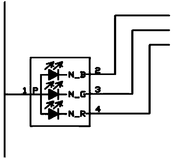
[0118] Figure 7a to Figure 7e is a schematic structural diagram of an LED display according to Embodiment 3 of the present invention; Figure 8a to Figure 8c is a schematic structural diagram of an LED display according to Embodiment 4 of the present invention. Such as Figure 7b and Figure 8b Shown are two implementations Figure 7a F covered by the dotted line and Figure 8a Partial enlarged view of H covered by the dotted line in the middle, Figure 7c The three primary color light-emitting diodes in the LED particles are directly integrated on the LED particles, while Figure 8c The three primary color light-emitting diodes in the middle LED particle are respectively packaged and integrated into the LED particle. In addition, the circuit connection relationship of the two implementations may be the same. in, Figure 7c The anode of each LED particle has 3 pins, respectively 1, 2, 3, corresponding to the anode of the internal R / G / B primary color light-emitting diod...
PUM
 Abstract
Description
Claims
Application Information
 - R&D
- Intellectual Property
- Life Sciences
- Materials
- Tech Scout
- Unparalleled Data Quality
- Higher Quality Content
- 60% Fewer Hallucinations
Browse by: Latest US Patents, China's latest patents, Technical Efficacy Thesaurus, Application Domain, Technology Topic, Popular Technical Reports.
© 2025 PatSnap. All rights reserved.Legal|Privacy policy|Modern Slavery Act Transparency Statement|Sitemap|About US| Contact US: help@patsnap.com


