Method for controlling light emission of a light emitting device, and a driving system implementing the method

a technology of light emitting devices and control methods, applied in static indicating devices, instruments, electroluminescent light sources, etc., can solve problems such as limiting the utilization rate and maximum brightness of led devices, and achieve the effect of higher utilization rate and refresh ra

Active Publication Date: 2015-03-19
MACROBLOCK INC
View PDF2 Cites 2 Cited by
  • Summary
  • Abstract
  • Description
  • Claims
  • Application Information

AI Technical Summary

Benefits of technology

[0013]Therefore, an object of the present invention is to provide a method of controlling light emission of a light emitting device. The method may cause the light emitting device to have relatively higher utilization rate and refresh rate.

Problems solved by technology

In this configuration, when 2kT21, there is a time period toff in which the LED device is in an idle state, thereby limiting a utilization rate and maximum brightness of the LED device.

Method used


Image

  • Method for controlling light emission of a light emitting device, and a driving system implementing the method
  • Method for controlling light emission of a light emitting device, and a driving system implementing the method
  • Method for controlling light emission of a light emitting device, and a driving system implementing the method

Examples


Embodiment Construction

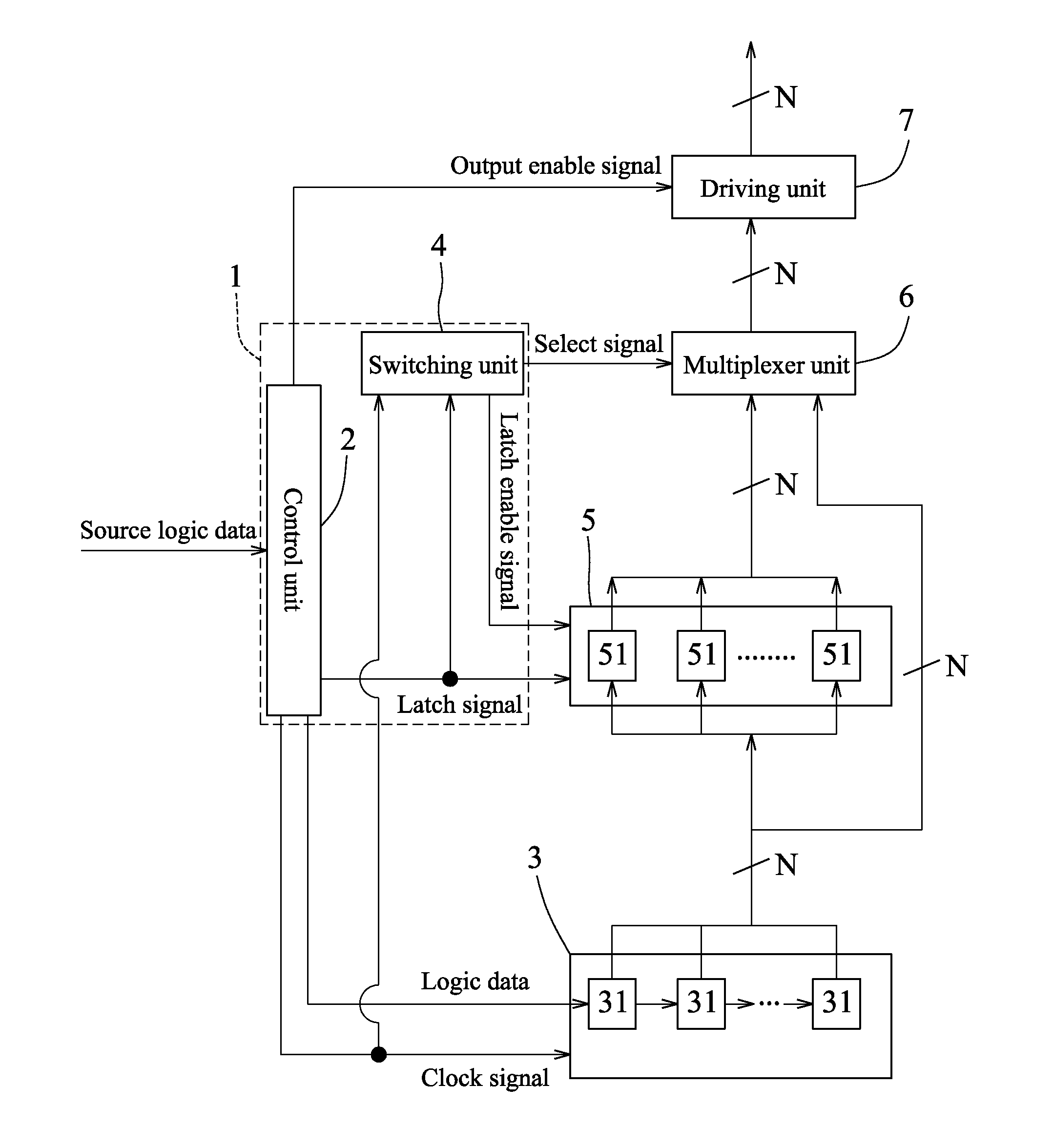
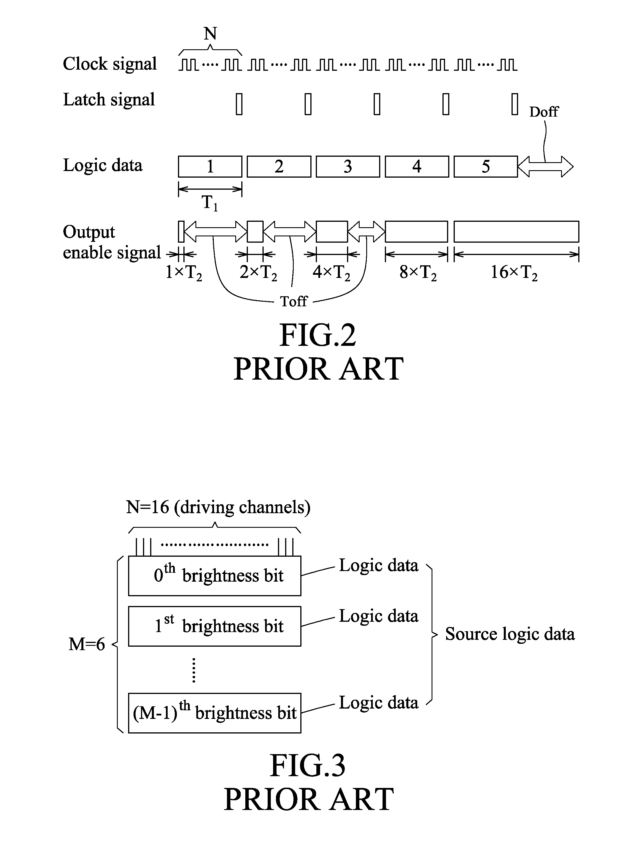
[0040]Referring to FIGS. 3 and 4, a first preferred embodiment of a driving system for a light emitting device (e.g., a light emitting diode (LED) device, which is not shown) according to this invention has a number N of driving channels to drive, for example, LEDs of the light emitting device, where N is an integer and N≧1. The driving system includes a control block 1, a shift register unit 3, a data latch unit 5, a multiplexer unit 6 and a driving unit 7. The control block 1 includes a control unit 2 and a switching unit 4. In practice, the switching unit 4 may be integrated with the control unit 2, may be integrated with the data latch unit 5 and the multiplexer unit 6, or may be an independent module, and the present invention should not be limited in this respect. The control unit 2 receives N sets of source logic data, each of which is composed a number M of brightness bits to indicate one of 2M levels of brightness, where M is an integer and M≧2. The brightness bits have dif...


PUM


Abstract

A driving system for a light emitting device includes a data latch unit to store first logic data, a shift register unit to store second logic data, a multiplexer unit to selectively output the first and second logic data, and a driving unit converting the logic data outputted by the multiplexer unit into a driving output that is provided to the light emitting device.

Description

CROSS-REFERENCE TO RELATED APPLICATION[0001]This application claims priority to Taiwanese Application No. 102133904, filed on Sep. 18, 2013.BACKGROUND OF THE INVENTION[0002]1. Field of the Invention[0003]The invention relates to a control method and a driving system, and more particularly to a control method and a driving system adapted for a light emitting device.[0004]2. Description of the Related Art[0005]Brightness of light emitted by an LED (light emitting diode) device is controlled by an LED driving system providing a constant current to the LED device for different periods of time, where the constant current refers to a constant current value within a unit time period.[0006]Referring to FIGS. 1 and 3, a conventional LED driving system has 16 driving channels to drive the LED device (not shown), and receives 16 sets of source logic data respectively corresponding to the 16 driving channels. Each set of source logic data is composed of 6 brightness bits to indicate one of 26 l...

Claims


Application Information

Patent Timeline
Patent Type & Authority Applications(United States)
IPC IPC(8): H05B33/08H05B37/02H05B44/00
CPCH05B37/0281H05B33/0845H05B45/00H05B47/10H05B45/10G09G3/3233H05B47/16
Inventor HSU, SHUN-YUANHSIEH, SHUN-CHING
Owner MACROBLOCK INC
Why Eureka
Try Eureka