Cam follower roller device

一种滚柱、凸轮的技术,应用在阀装置、传动装置、燃料喷射装置等方向,能够解决妨碍套管滑动、强度不足支撑体、套管变型等问题

Active Publication Date: 2014-06-11
AB SKF
View PDF6 Cites 12 Cited by
  • Summary
  • Abstract
  • Description
  • Claims
  • Application Information

AI Technical Summary

Problems solved by technology

Risk of insufficient strength to allow undesired movement of the support within the sleeve, and risk of excessive force or heat causing deformation of the sleeve when the support is installed, such as preventing the sleeve from sliding in its bore

Method used


Image

  • Cam follower roller device
  • Cam follower roller device
  • Cam follower roller device

Examples


Embodiment Construction

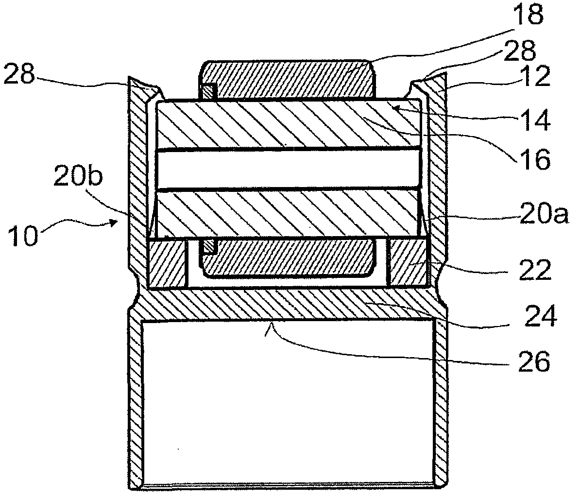
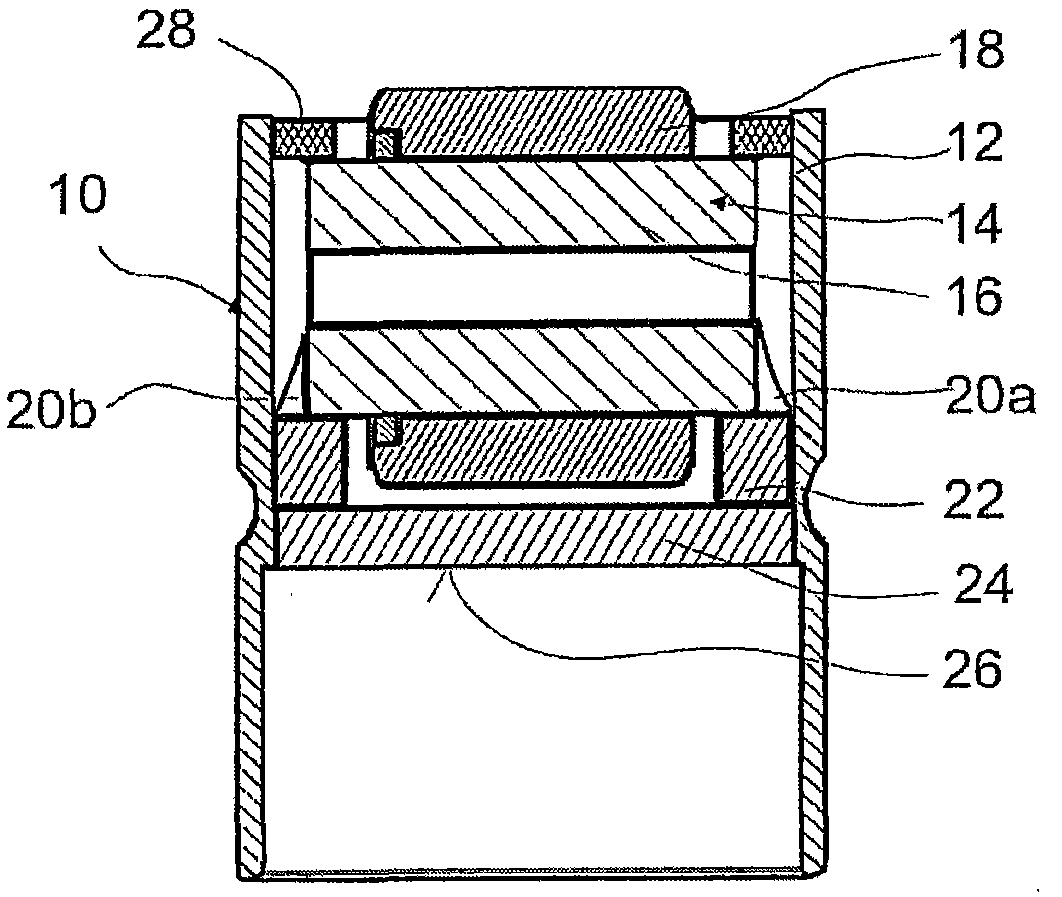
[0035] figure 1 is an axial sectional view of the cam traveling roller device according to the first embodiment of the present invention. The device comprises a tappet 10 having a sleeve 12 with a circular opening receiving the main part of a roller 14 . Roller 14 is rotatably mounted within bushing 12 and includes a portion axially projecting from an opening of bushing 12 . The portion is arranged to cooperate with a cam (not shown). The device can be used in a fuel injection pump of an internal combustion engine.

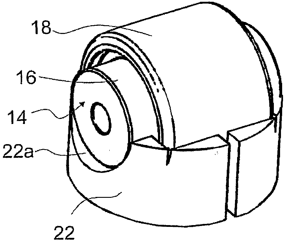
[0036] Roller 14 includes a spindle 16 and a cylinder 18 . The ends of the spindle 16 protrude from the lateral surface of the cylinder 18 of the roller 14 . The cylinder 18 may be rotatably mounted on the mandrel 16 by a bearing or needle bearing arrangement, or may be mounted in a fixed manner by upsetting or rolling. Alternatively, the spindle 16 and cylinder 18 of the rollers may be made in one piece.

[0037] The roller 14 support 22 is arranged on a ba...


PUM


Abstract

The present invention proposes a cam follower roller device, in particular for a fuel injection pump of an internal combustion engine, including a tappet with a sleeve having an opening for partially accommodating a roller, a roller mounted rotatably in the sleeve and having a portion which protrudes axially from the opening of the sleeve provided to cooperate with a cam, and a roller support body housed in the sleeve. The roller includes a cylindrical spindle and a cylindrical body, the ends of the spindle projecting from the lateral faces of the body. It is proposed that the support body includes supports open towards the opening of the sleeve and supporting the ends of the spindle.

Description

technical field [0001] The invention relates to the field of cam follower roller arrangements for use in automotive or industrial applications. [0002] An advantageous application of the invention relates to the use of the cam follower arrangement in fuel injection pumps for internal combustion engines, in particular in motor vehicles such as cars or trucks. Background technique [0003] This type of device consists of a tappet and a roller mounted rotatably on the tappet for cooperating with a cam that is synchronized with the camshaft of an internal combustion engine in such a way that the rotation of the camshaft causes bearings on the The pump piston on the tappet moves periodically so that the fuel can be dispensed. [0004] The tappet of the device is usually embodied as a single counter piece, for example produced by cold forging. The rollers of the device are usually rotatably mounted on tappets by separate spindles. The mandrel is conventionally mounted on the t...

Claims


Application Information

Patent Timeline
Patent Type & Authority Applications(China)
IPC IPC(8): F02M59/44
CPCF01L2105/02F01L2103/00F02M59/102F16H25/14F04B1/0439F04B1/0426F01L2105/00F01L1/14F01L2101/00F04B1/0404F01L2107/00Y10T74/2107Y10T29/49547F01L2305/02F01L2307/00F01L2301/00F01L2303/00F01L2305/00
Inventor B·豪维斯普里N·范德梅
Owner AB SKF
Why Eureka
Try Eureka