
Eccentric water tank type hydraulic self flushing intercepting and accumulating door

A self-flushing, water tank technology, applied to drain pipe flushing devices, self-flushing blocking and storage doors. It can solve the problems of increasing equipment cost, increasing cost, complex structure, etc., and achieving the effect of easy transformation

Active Publication Date: 2014-06-11
WUHAN SHENGYU DRAINING SYST
View PDF5 Cites 9 Cited by
  • Summary
  • Abstract
  • Description
  • Claims
  • Application Information

AI Technical Summary

Problems solved by technology

Existing pipe cleaning devices are generally scraping tools for pipe wall dirt or cleaning equipment with complex structures
Not only manual operation is required, but some equipment costs are high
There is also a drive device used as a drain pipe flushing gate for opening the gate. The opening and closing of the gate by the drive device will inevitably increase the cost of equipment, and at the same time it is necessary to add a set of devices for monitoring the internal flow of the drain pipe, which further improves the performance of the gate. cost and are more difficult to maintain

Method used


Image

  • Eccentric water tank type hydraulic self flushing intercepting and accumulating door
  • Eccentric water tank type hydraulic self flushing intercepting and accumulating door
  • Eccentric water tank type hydraulic self flushing intercepting and accumulating door

Examples


Embodiment Construction

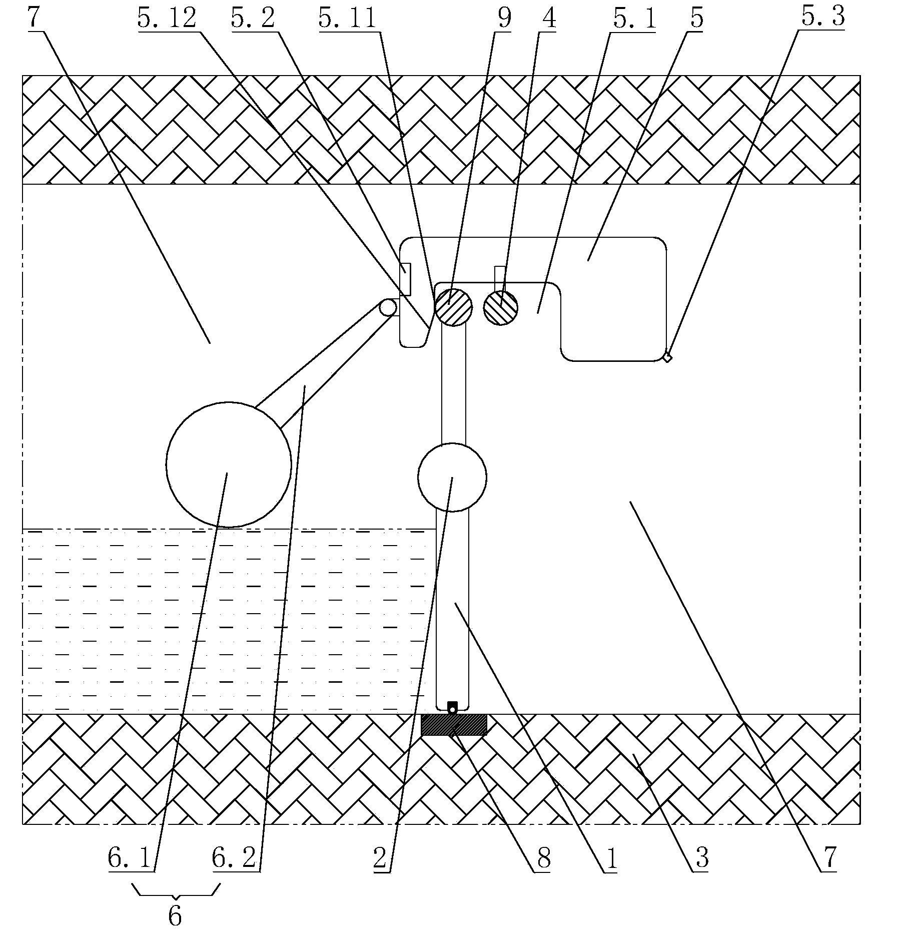
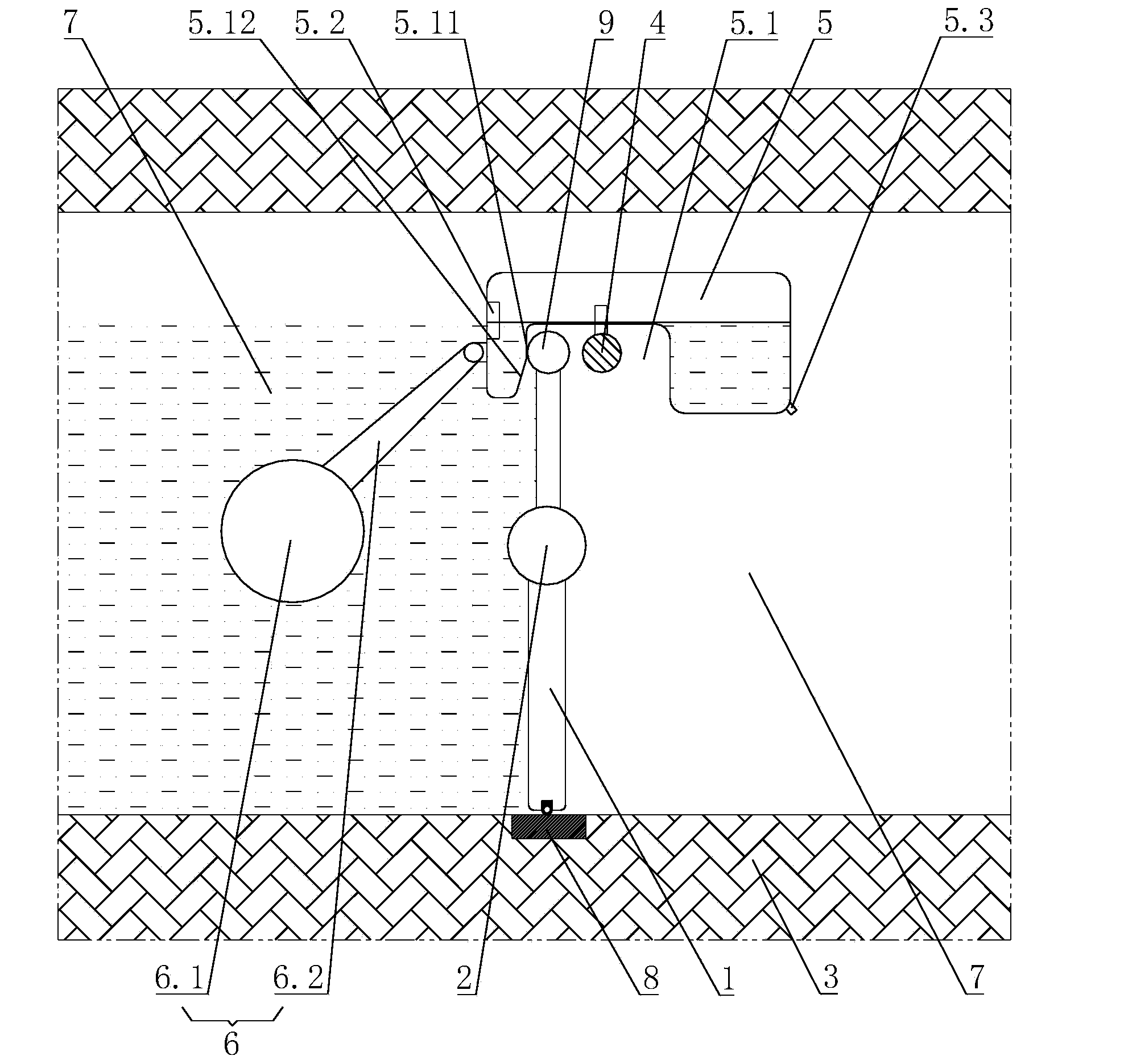
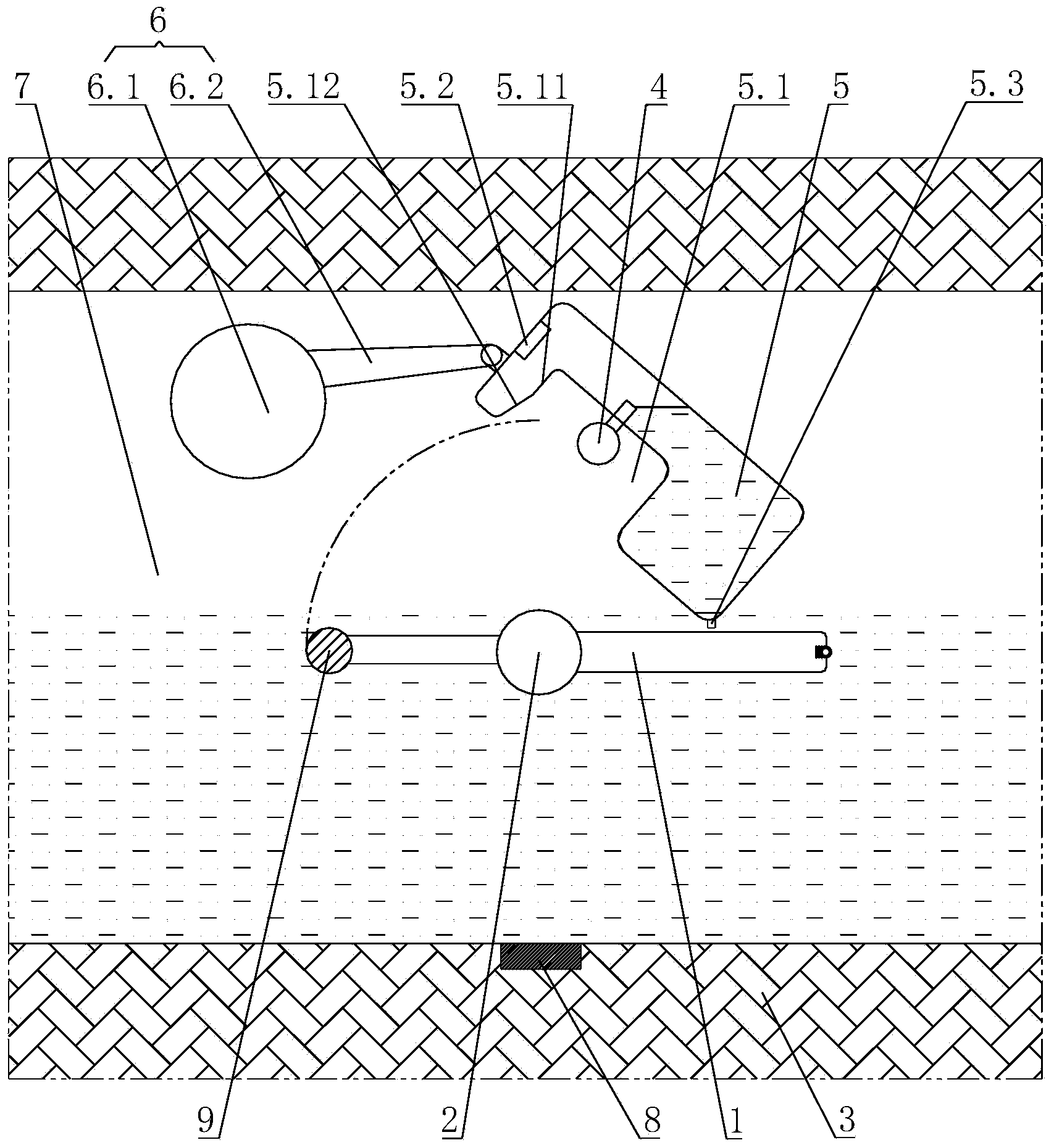
[0021] Such as Figure 1 to Figure 4 As shown, the fixed type hydraulic self-flushing retaining door of the eccentric water tank includes a door panel 1, the upper part of the door panel 1 is provided with a rotating shaft 2, and the two ends of the rotating shaft 2 extend into the drainage pipe matrix 3; the door panel 1 is located at the lower part of the rotating shaft 2 The gravity is greater than the gravity on the upper part of the rotating shaft 2; a connecting shaft 4 is provided downstream of the door panel 1, and both ends of the connecting shaft 4 extend into the drainage pipe matrix 3; an eccentric water tank 5 is connected to the connecting shaft 4 in rotation, so The bottom of the eccentric water tank 5 is provided with a card slot 5.1, the card slot 5.1 is arranged parallel to the connecting shaft 4, and the card slot 5.1 is offset to the upstream of the door panel 1; the top of the door panel 1 can be engaged in the card slot 5.1 inside; one end of the eccentri...


PUM


Abstract

The invention discloses an eccentric water tank type hydraulic self flushing intercepting and accumulating door, which comprises a door plate, wherein a rotating shaft is arranged at the upper part of the door plate, the two ends of the rotating shaft extend into a base body of a water discharge pipeline, the gravity of the part, positioned under the rotating shaft, of the door plate is greater than the gravity of the part positioned above the rotating shaft, a connecting shaft is arranged at the downstream of the door plate, the two ends of the connecting shaft extend into the base body of the water discharge pipeline, an eccentric water tank is rotationally connected onto the connecting shaft, the bottom of the eccentric water tank is provided with a clamp groove, the clamp groove is arranged parallel to the connecting shaft, and in addition, the clamp groove deviates towards the upper steam of the door plate; the top of the door plate can be clamped in the clamp groove, one end of the eccentric water tank is positioned at the upper stream of the door plate, and in addition, a weight balancing element is fixedly connected onto the side wall of the end; one end, positioned at the upper stream of the door plate, of the eccentric water tank is provided with a water inlet, and one end, positioned at the downstream of the door plate, of the eccentric water tank is provided with a water outlet. The water flow in the water discharge pipeline is used as driving force, the opening and the closing of the intercepting and accumulating door can be realized without other external force effects, the structure is simple, the installation is easy, and meanwhile, the transformation on the existing water discharge pipeline is easy.

Description

technical field [0001] The utility model belongs to the technical field of pipeline dredging, in particular to a drainage pipeline flushing device, in particular to a hydraulic self-flushing blocking storage door. Background technique [0002] Drainage pipes need to be cleaned regularly, especially in the combined drainage pipes where rainwater and sewage are discharged together, it is easy to cause pollutants to accumulate inside the pipes, forming blockages inside the pipes, and causing the sewage inside the pipes to ferment and emit odor. At the same time, since the flow of sewage inside the pipeline is smaller than the design flow, it will inevitably lead to the deposition of debris, which will cause functional loss and environmental problems to the pipeline itself and public waters. For this reason, some simple and economical methods need to be adopted to regularly clean the pipes to ensure the smoothness of the drainage pipes. Existing pipe cleaning devices are genera...

Claims


Application Information

Patent Timeline
Patent Type & Authority Applications(China)
IPC IPC(8): E03F9/00E03F7/02
Inventor 周超何锐
Owner WUHAN SHENGYU DRAINING SYST
Learn More