Pneumatic control rivet feeding mechanism for automatic rivet feeding riveting machine

A riveting machine and nail feeding technology, which is applied in the field of riveting equipment, can solve the problems of unsuccessful feeding, complex structural parts, high length of compression spring 7, etc., and achieve the effect of stable feeding and simple structural parts

Inactive Publication Date: 2014-06-11
WUHAN RIVET MACHINERY
View PDF0 Cites 0 Cited by
  • Summary
  • Abstract
  • Description
  • Claims
  • Application Information

AI Technical Summary

Problems solved by technology

The extension and contraction of the mechanical pendulum type feeding frame are controlled by the up and down movement of the pendulum 3 and the expansion and contraction of the compression spring 7. The structural parts are complex, and the stroke of the pendulum 3 needs to be adjusted during assembly, which has a greater impact on the length of the compression spring 7. high demands
In addition, when the rivet heads overlap or do not completely fall into the notch of the feed frame, the mechanical swing rod type rivet feed will fail to feed, resulting in empty punching and damage to the surface appearance of the workpiece

Method used


Image

  • Pneumatic control rivet feeding mechanism for automatic rivet feeding riveting machine
  • Pneumatic control rivet feeding mechanism for automatic rivet feeding riveting machine
  • Pneumatic control rivet feeding mechanism for automatic rivet feeding riveting machine

Examples


Embodiment Construction

[0012] The present invention will be further described in detail below in conjunction with the accompanying drawings and specific embodiments.

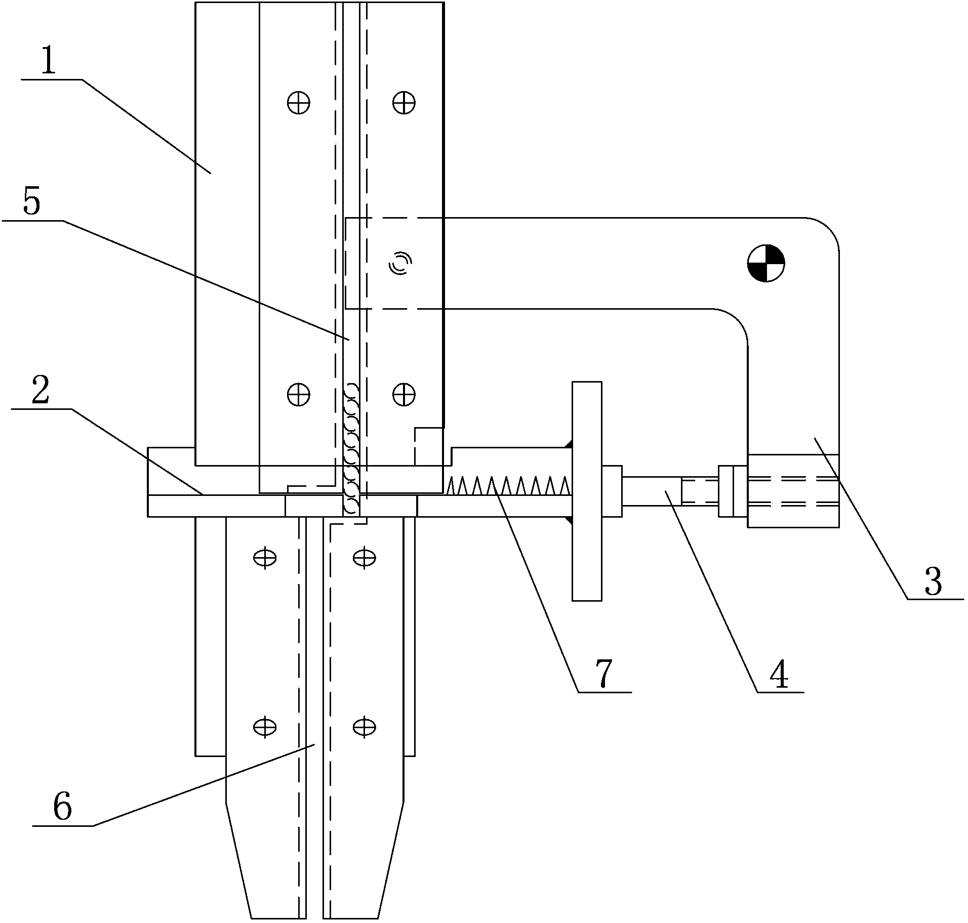
[0013] figure 1 The mechanical pendulum-type nail-feeding mechanism of the existing automatic nail-feeding riveting machine shown has been introduced in detail in the background art, and will not be repeated here.

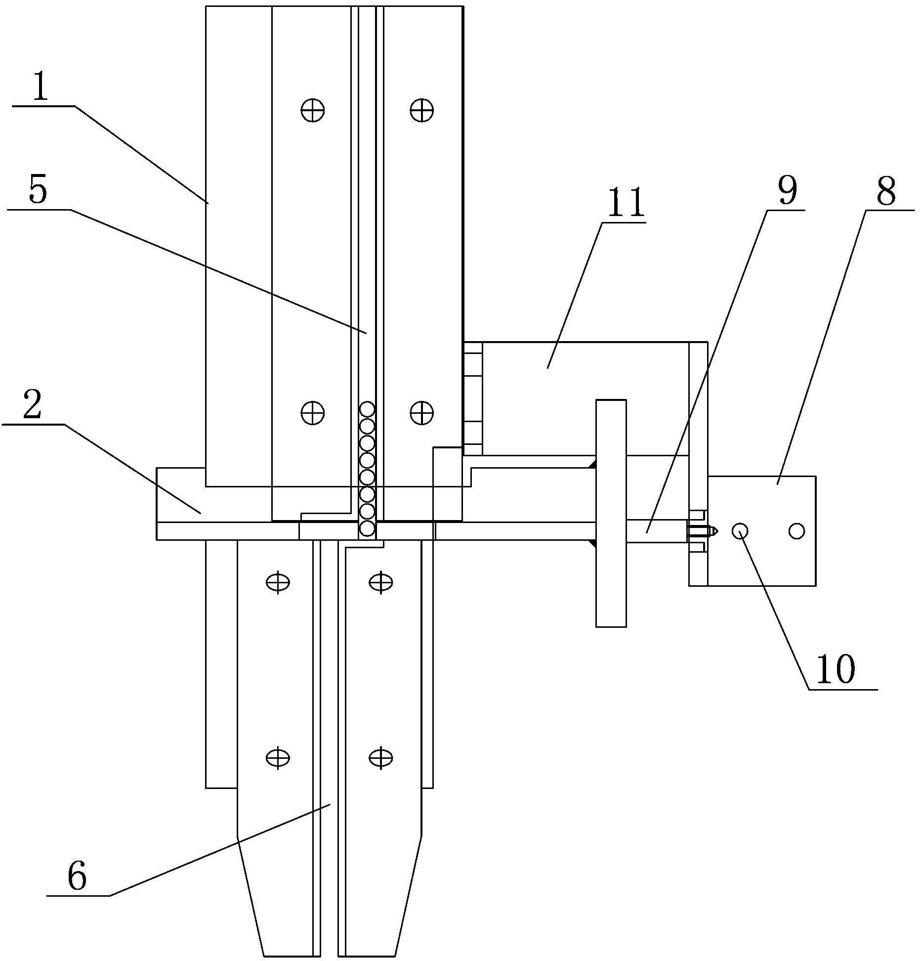
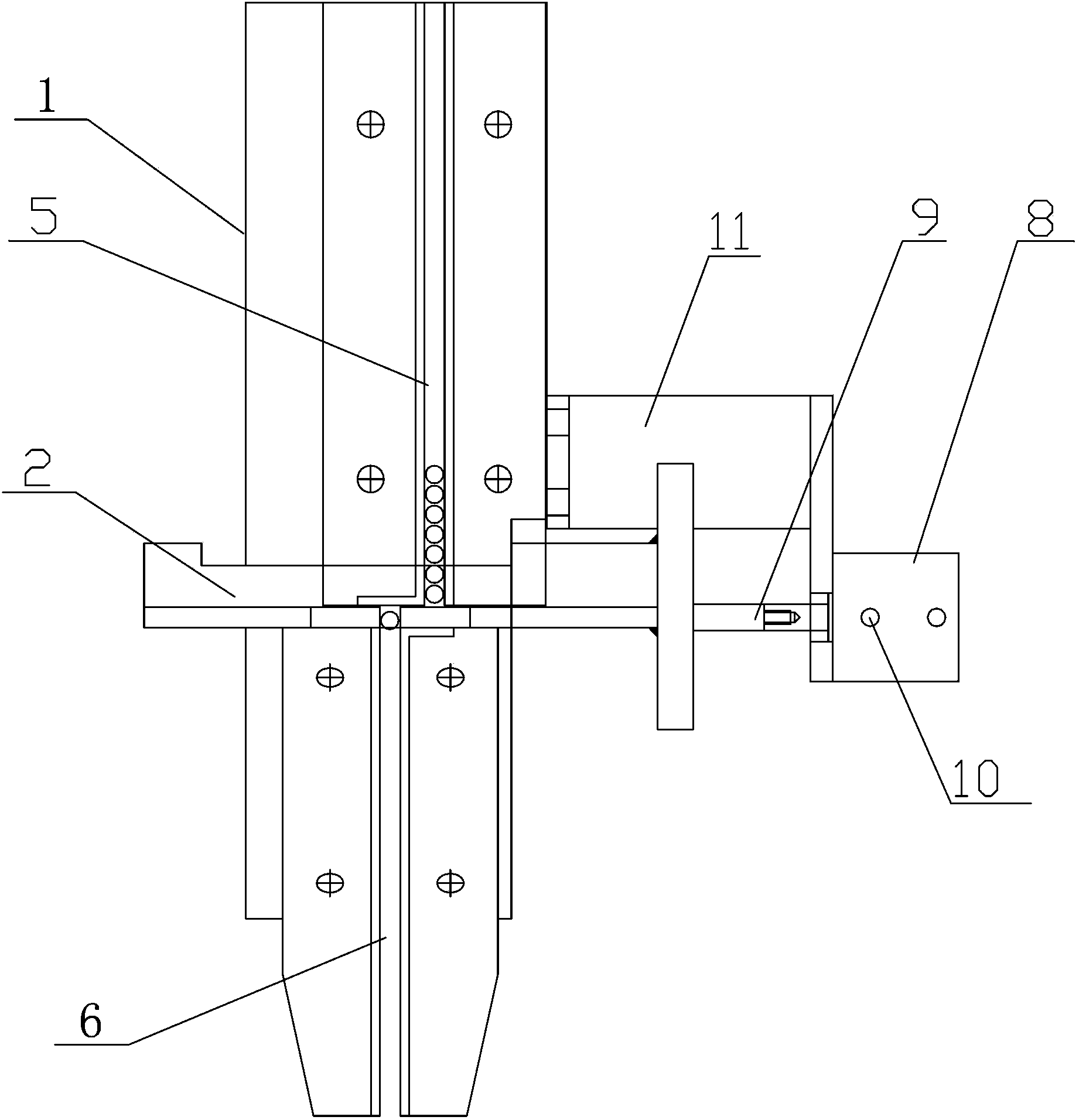
[0014] Figure 2~3 The air-controlled nail-feeding mechanism of the automatic nail-feeding riveting machine shown includes a bracket 1, a feeding rack 2, an upper guide rail 5 and a lower guide rail 6 located above and below the feeding rack 2, respectively. The side of feed frame 2 is provided with cylinder 8, and the piston push rod 9 of cylinder 8 is connected with the side end surface of feed frame 2, and the feeding direction of piston push rod 9 is parallel with feed frame 2. The cylinder 8 is connected to the bracket 1 through the cylinder bracket 11 , and the air cylinder 8 is provided with a ventilation hole 10 ...


PUM


Abstract

The invention discloses a pneumatic control rivet feeding mechanism for an automatic rivet feeding riveting machine, which comprises a bracket, a feeding frame and an upper guide rail and a lower guide rail which are respectively positioned at the upper and lower parts of the feeding frame. A cylinder is arranged beside the feeding frame; a piston ejector rod of the cylinder is connected with the side end face of the feeding frame; and the piston ejector rod is in parallel to the feeding direction of the feeding frame. The pneumatic control rivet feeding mechanism disclosed by the invention utilizes compressed air to replace the effects of a compression spring, enables the feeding frame to extend and retract by air suction and exhaust, has a simple structure, adopts simple parts and only needs to regulate the distance of the ejector rod in the assembling process. The pneumatic control rivet feeding mechanism is stable to feed, can ensure that the rivet feeding operation is successful each time, cannot cause idle beating and cannot damage the surface appearance of a workpiece.

Description

technical field [0001] The invention relates to riveting equipment, in particular to an air-controlled nail feeding mechanism of an automatic nail feeding riveting machine. Background technique [0002] Automatic rivet feeding riveting machine is an automatic riveting equipment that can automatically complete rivet feeding, rivet conveying, rivet placement and riveting through mechanical devices, and its efficiency is several times that of ordinary riveting equipment. [0003] The stability of riveting automation depends on the success rate of rivet feeding, and the success rate of rivet feeding depends on the structure of rivet feeding. [0004] The currently commonly used nail feeding mechanism is a mechanical pendulum type, such as figure 1 As shown, it includes a support 1, a feeding frame 2, a swing rod 3, a screw 4 connected to the swing rod 3, an upper guide rail 5 and a lower guide rail 6 that are used for rivet transportation above and below the feeding frame 2, an...

Claims


Application Information

Patent Timeline
IPC IPC(8): B21J15/32
Inventor 杨诗超
Owner WUHAN RIVET MACHINERY
Why Eureka
Try Eureka