
Construction method and special hole forming machine of concrete cylinder buried in soft foundation

A concrete and soft foundation technology, applied in earthwork drilling, infrastructure engineering, liquid/gas jet drilling, etc., can solve the problems of long construction hours, high equipment requirements, and high equipment cost of concrete cylinders, and achieve easy compression , increase the construction depth, improve the effect of construction speed

Inactive Publication Date: 2014-06-04
宁波市鄞州元典知识产权服务有限公司
View PDF7 Cites 3 Cited by
  • Summary
  • Abstract
  • Description
  • Claims
  • Application Information

AI Technical Summary

Problems solved by technology

However, the construction method of this double-steel tube structure has relatively high requirements on equipment, and it needs to apply a lot of pressure to press the casing into the soil, which makes the construction equipment cost high and the construction time of the concrete cylinder is long.

Method used

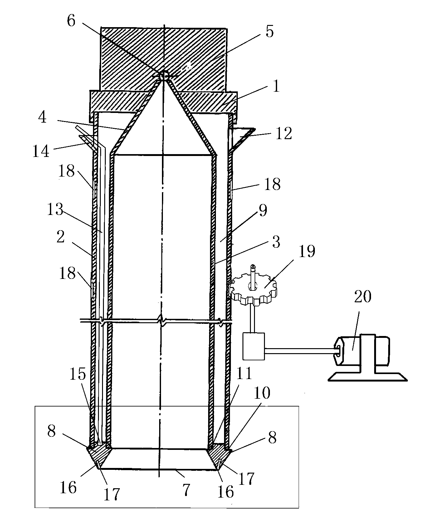

Image

  • Construction method and special hole forming machine of concrete cylinder buried in soft foundation
  • Construction method and special hole forming machine of concrete cylinder buried in soft foundation
  • Construction method and special hole forming machine of concrete cylinder buried in soft foundation

Examples


Embodiment Construction

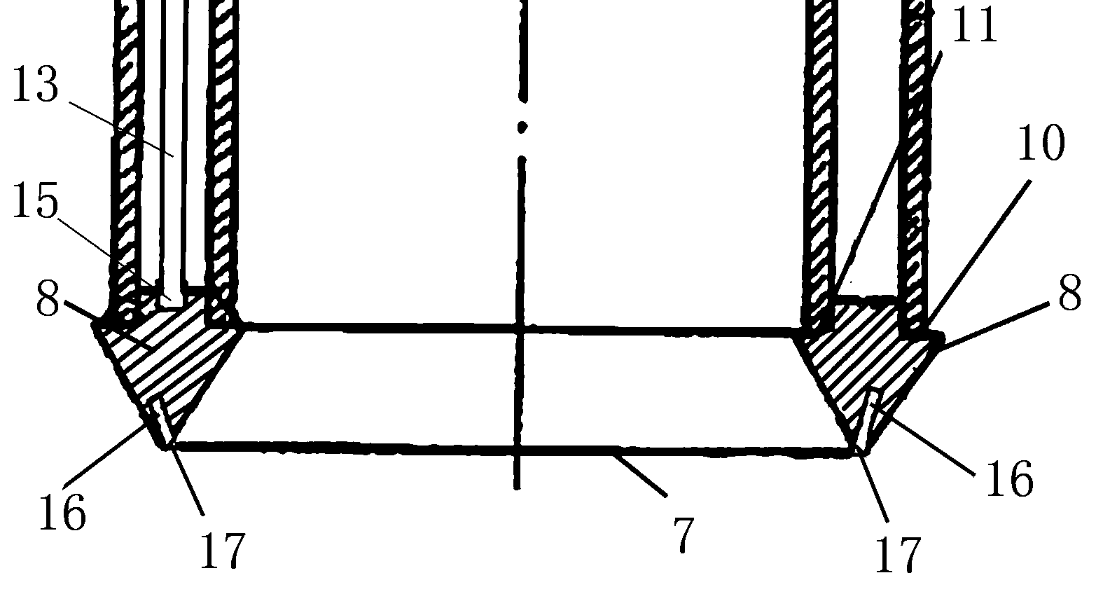
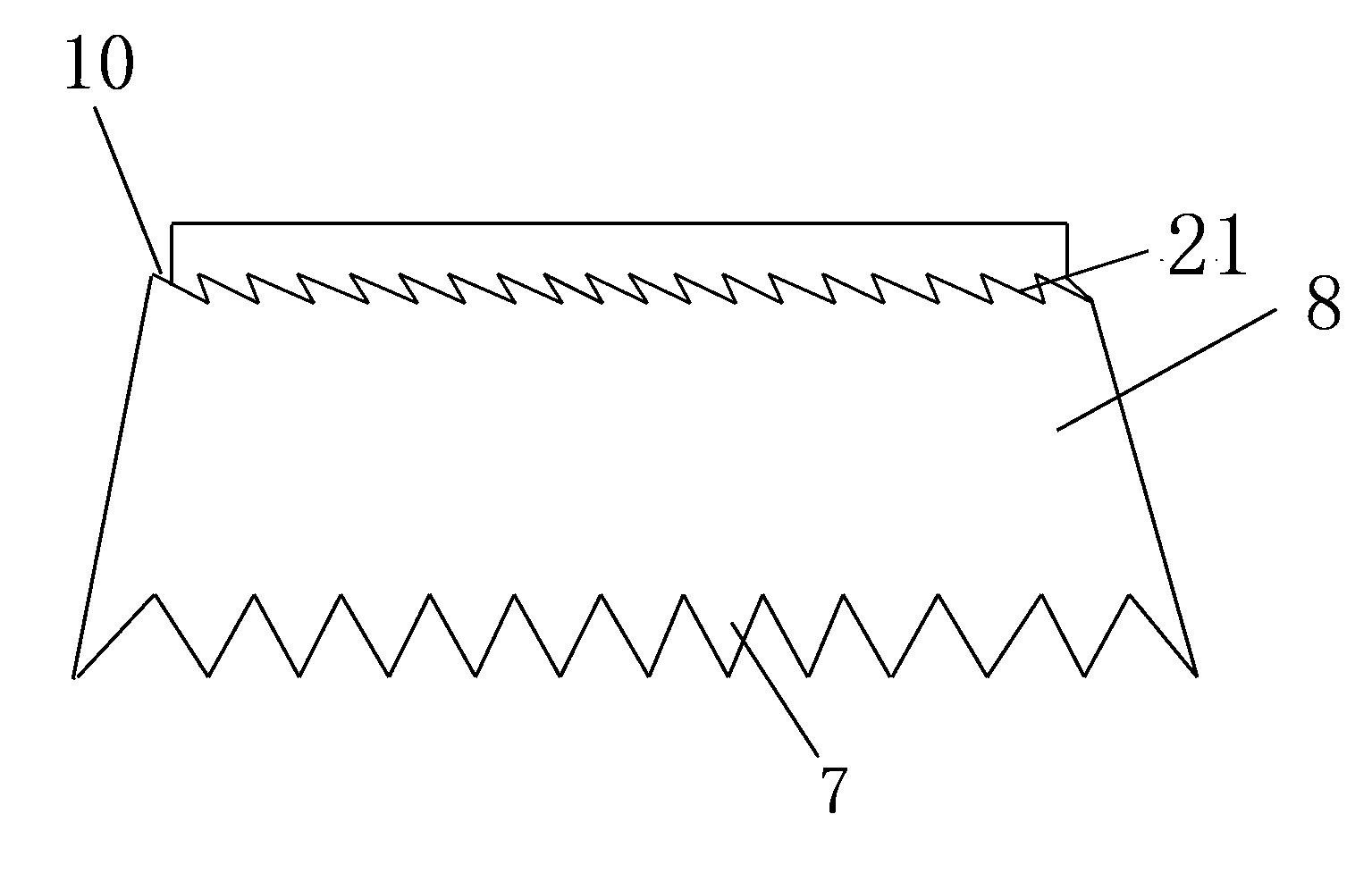
[0017] See attached picture. This embodiment includes a gland 1, an inner wall sleeve 3 and an outer wall sleeve 2. The outer wall sleeve 2 is provided with a pouring port 12 on the side; the inner wall sleeve 3 and the outer wall sleeve 2 The cover 1 is connected, and the upper end of the inner protective wall sleeve 3 forms a tapered tube 4 which is inserted into the pressure head 5 placed above the gland 1 and communicates with the mud hole 6 in the pressure head 5; The lower end of the tube 3 and the outer protective wall sleeve 2 is sheathed with a barrel shoe 8 with a cylindrical structure. The lower end of the barrel shoe 8 forms a cutting edge 7; the upper end of the barrel shoe 8 has a "convex" shape in radial section and has a ring shape. The outer bearing surface 10 and the inner bearing surface 11; the boot 8 is sleeved in the bore 9 between the inner wall sleeve 3 and the outer wall sleeve 2; the cutting edge 7 at the lower end of the boot 8 is serrated The upper ...


PUM


Abstract

The invention discloses a construction method and a special hole forming machine of a concrete cylinder buried in a soft foundation. The special hole forming machine comprises an inner protection casing and an outer protection casing, wherein the upper end of the inner protection casing is connected with the upper end of the outer protection casing through a gland, and a taper tube formed at the upper end of the inner protection casing is inserted in a force application pressure head placed on the gland; the lower end face of the inner protection casing and the lower end face of the outer protection casing are matched with an inner bearing surface and an outer bearing surface of the upper end of a cylinder boot through ratchet structures respectively; the cutting edge at the lower end of the cylinder boot is in a sawtooth shape; a tooth ring is fixed on the periphery of the outer protection casing; the special hole forming machine is further provided with a driving mechanism which comprises a gear meshed with the tooth ring on the periphery of the outer protecting casing; the special hole forming machine also comprises a high-pressure water pipe arranged in a cylinder hole between the inner protection casing and the outer protection casing; the upper end of the cylinder boot is provided with a water inlet, and the lower end of the high-pressure water pipe is connected with the water inlet in a sealed mode; the lower end of the cylinder boot is provided with a plurality of water outlets which are communicated with the water inlet waterways in the cylinder boot. By means of the construction method and the special hole forming machine, construction speed can be increased, and the construction depth can be increased; meanwhile, pressure needing to be applied by a pressure applying device is reduced, and therefore the requirement for construction equipment is lowered.

Description

Technical field [0001] The invention belongs to the field of building construction equipment, and particularly relates to a construction method of a concrete cylinder buried in a soft foundation and a dedicated hole former. Background technique [0002] The concrete tube buried in the soft foundation has many applications in the underground construction process. For example, the bored hollow pile in the foundation construction and the wall protection of the underground caisson are all thin-walled concrete tubes. The traditional concrete tube pile construction method is to use a single cylinder to inject concrete. This construction method requires a large amount of soil to be discharged during the hole forming process, and the amount of earth borrowing is large; similarly, a large amount of concrete is required during the pouring process, which affects the engineering Progress, and increased engineering costs. [0003] In the patent number 98113070.4, the invention patent titled "C...

Claims


Application Information

Patent Timeline
Patent Type & Authority Applications(China)
IPC IPC(8): E02D5/38E21B17/00E21B17/14E21B7/18
Inventor 朱枫
Owner 宁波市鄞州元典知识产权服务有限公司
Learn More