Method for checking current transformers for differential protection

A current transformer and differential protection technology, applied in the field of power system equipment calibration

Active Publication Date: 2014-05-28
STATE GRID CORP OF CHINA +1
View PDF4 Cites 9 Cited by
  • Summary
  • Abstract
  • Description
  • Claims
  • Application Information

AI Technical Summary

Problems solved by technology

[0006] In order to solve the current transformer used for differential protection in the checking process, not only should a single current transformer meet the requirements, but also the characteristics of the current transformers on each side cooperate with each other. A Calibration Method of Current Transformer for Differential Protection

Method used


Image

  • Method for checking current transformers for differential protection
  • Method for checking current transformers for differential protection
  • Method for checking current transformers for differential protection

Examples


Embodiment Construction

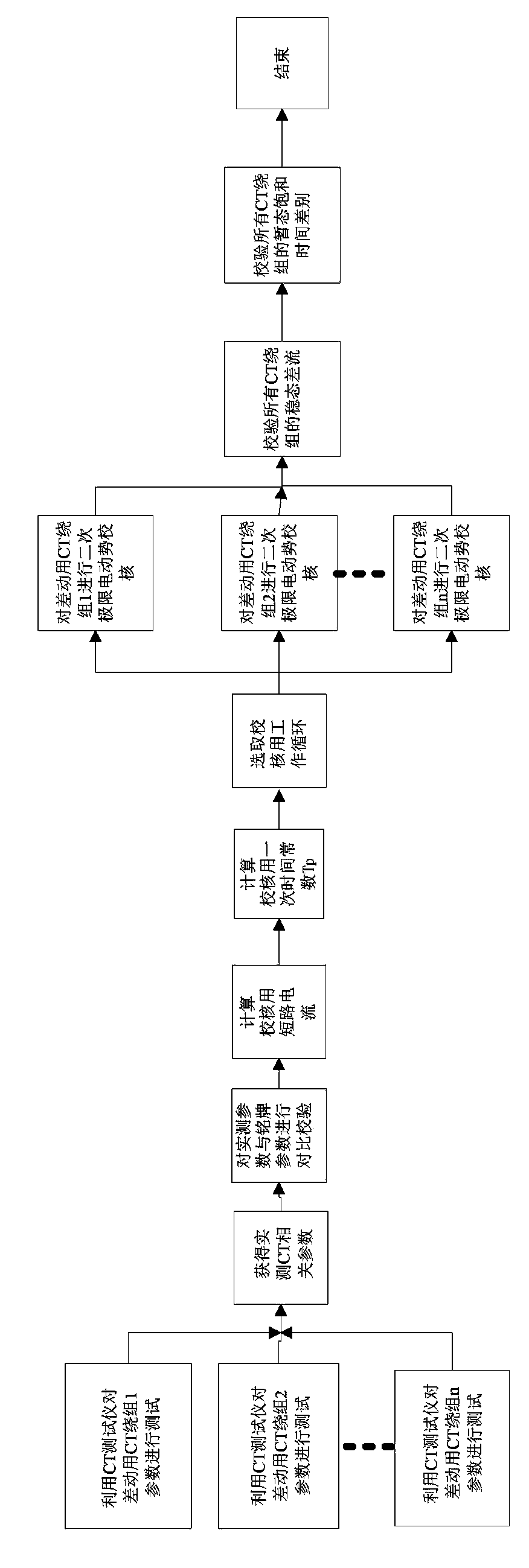
[0032] see figure 1 , the verification method of the current transformer for differential protection of the present invention, in the whole verification process, it is necessary to first obtain the relevant current transformer parameters through actual testing, because although there are relevant parameters of the current transformer on the nameplate, the current transformer Whether the parameters change during the running process also needs to be determined through testing. Therefore, it is necessary to use the current transformer tester to test the winding parameters of multiple differential current transformers to obtain the measured current transformer parameters. The measured current transformer parameters include at least the rated short-circuit current multiple K ssc , Current transformer direct resistance R ct , Current transformer secondary load R b As well as the current transformer excitation characteristic curve, the above parameters need to be used in the subseq...


PUM


Abstract

The invention provides a method for checking current transformers for differential protection. The method aims to solve the problem that in the checking process of existing current transformers for differential protection, whether a single current transformer meets requirements should be considered, the cooperating conditions of the characteristics of the current transformers on all sides should also be considered. According to the method for checking the current transformers for differential protection, the properties of the current transformers are considered, and the performance difference between the current transformers is checked at the same time so that it can be guaranteed that a current transformer winding put into operation can meet the requirement of field operation; during actual operation, the method has quite great significance in the current transformers for differential protection, and whether the current transformers can meet the needs of field operation can be judged more accurately.

Description

technical field [0001] The present invention relates to the related technical field of power system equipment calibration, and furthermore, relates to a calibration method of a current transformer, especially a calibration method of a current transformer for differential protection. Background technique [0002] The current transformer widely used at this stage is an electromagnetic current transformer, which has an iron core, and the iron core of the current transformer has nonlinear characteristics. The primary current is very large, the primary current contains a large DC component, the iron core has a large residual magnetism, and the secondary load is large, etc., which may cause severe saturation of the current transformer core, and the operating point will enter the saturation part of the magnetization curve. The excitation current increases by dozens of times or even higher, which seriously distorts the value and waveform of the secondary current. This will cause in...

Claims


Application Information

Patent Timeline
IPC IPC(8): G01R35/02
Inventor 高博丁津津汪玉罗亚桥郑国强李远松谢毓广徐斌戴申华俞斌
Owner STATE GRID CORP OF CHINA
Why Eureka
Try Eureka