
Scanning interferometer device for measuring imaging Fourier transform spectrum

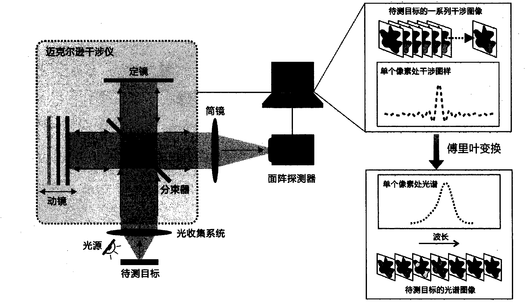
A technology of Fourier transform and spectral measurement, which is applied in the field of scanning interferometer device for imaging Fourier transform spectral measurement, which can solve the problems of weak interference, undetectable, increased scanning interferometer space, etc., and achieve the high requirement of reducing the dynamic range , Overcoming the beam tilt and reducing the overall volume

Inactive Publication Date: 2014-05-28
李剑平
View PDF5 Cites 11 Cited by
  • Summary
  • Abstract
  • Description
  • Claims
  • Application Information

AI Technical Summary

Problems solved by technology

This greatly increases the space occupied by the scanning interferometer using it as a moving mirror, which is not conducive to the miniaturization and compaction of the imaging Fourier transform spectrometer constructed based on it.
[0006] In addition, the interference peak light intensity formed by the traditional imaging Fourier transform spectrometer at the brightest pixel and the darkest pixel of the target image may span a huge range, which poses extremely strict requirements on the dynamic range of the area array detector. requirements
If the pixel dynamic range of the area detector is not large enough, it will easily lead to the saturation of the interference signal measurement at the bright pixel or the interference at the dark pixel is too weak to be detected
thereby degrading the spectral measurement of the spectrometer

Method used


Image

  • Scanning interferometer device for measuring imaging Fourier transform spectrum
  • Scanning interferometer device for measuring imaging Fourier transform spectrum
  • Scanning interferometer device for measuring imaging Fourier transform spectrum

Examples


Embodiment Construction

[0023] In order to clearly illustrate the technical features of the solution, the solution will be described below in conjunction with the accompanying drawings and specific implementation methods.

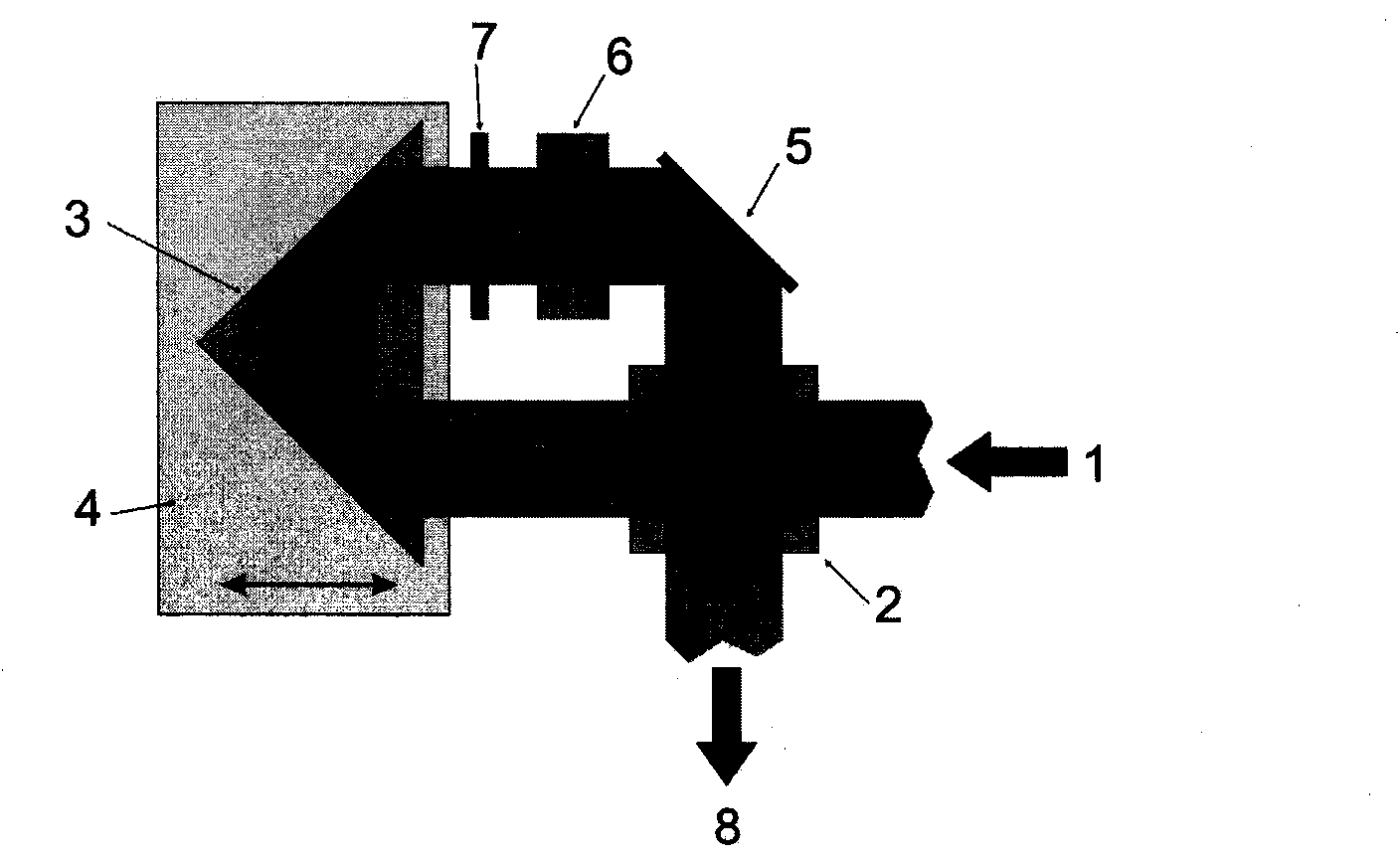
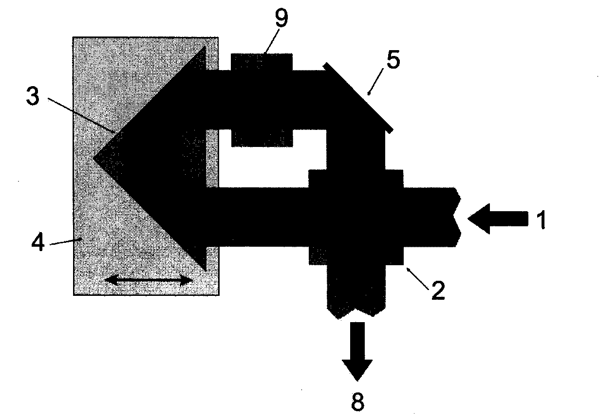
[0024] figure 2Shown is a top view of a scanning interferometer device for imaging Fourier transform spectrum measurement according to the present invention: the light emitted by the target to be measured is collected by the light collection system at the front end of the imaging Fourier transform spectrometer and collimated into an incident beam 1, 1 enters the spectrometer and shoots to the cube beam splitter 2; the reflected beam passing through 2 is reflected by the 45° plane mirror 5, and the optical path is folded by 90° and shoots to the compensation plate 6. After the beam passes through 6, it is perpendicular to the double-sided plane reflection The reflective surface on one side of the mirror 7 is finally vertically reflected by the fixed 7, and returns to 2 along the o...


PUM


Abstract

The invention discloses a scanning interferometer device for measuring an imaging Fourier transform spectrum. The scanning interferometer device is composed of a beam splitter, a movable arm and a static arm. The scanning interferometer device is characterized in that the movable arm and the static arm are in light path folding structures and share a fixed double-faced plane reflecting mirror; two reflecting surfaces of the plane reflecting mirror are respectively used for vertically reflecting incident light beams of the movable arm and the static arm to the beam splitter; a compensation plate is inserted into a light path of the static arm to compensate a light path difference between the two arms. The folding structure of a light path of the movable arm can be used for overcoming the inclined and transverse movement problems of light beams in the movable mirror scanning process of a Michelson interferometer; the compensation plate is inserted into the light path of the static arm to reduce the high requirements on a dynamic range of an area array detector by the measurement of the imaging Fourier transform spectrum; the light paths of the two arms are folded and one double-faced plane reflection mirror is commonly used so as to reduce the volume of a scanning interferometer. A constructed imaging Fourier transform spectrometer is very small-sized and compact, and has good application benefits in a plurality of fields including physics, biology, chemistry, medicine, pharmacy, foods, environmental friendliness, remote sensing, spaceflight and the like.

Description

technical field [0001] The present application relates to a scanning interferometer device for imaging Fourier transform spectroscopy. Background technique [0002] The imaging Fourier transform spectrometer uses an area array detector instead of a single point detector, which expands the spatial resolution capability of the ordinary Fourier transform spectrometer, and can simultaneously acquire two-dimensional spatial image information and one-dimensional spectral information of the target to be measured to realize imaging Spectral (or spectral imaging) measurements. Under proper design, the imaging Fourier transform spectrometer can well inherit several spectral measurement advantages of the general Fourier transform spectrometer, such as: 1 multi-channel, 2 high luminous flux, 3 high spectral measurement accuracy, 4 wide measurement band, 5 high / tunable spectral resolution, 6 full-band resolution consistent. The rich spatial and spectral information acquisition capabili...

Claims


Application Information

Patent Timeline
Patent Type & Authority Applications(China)
IPC IPC(8): G01J3/45
Inventor 李剑平
Owner 李剑平
Learn More