Underground hydraulic piston pump

A hydraulic piston and double piston technology, applied in pumps, liquid displacement machinery, pumps with flexible working elements, etc., can solve problems such as reducing pump efficiency, increasing processing equipment and processing costs, and grinding production strings, etc. Achieve the effects of reducing production costs, increasing ultimate recovery, and increasing pump efficiency

Inactive Publication Date: 2014-05-28
北京万普瑞能源技术有限公司
View PDF5 Cites 5 Cited by
  • Summary
  • Abstract
  • Description
  • Claims
  • Application Information

AI Technical Summary

Problems solved by technology

[0002] In oil and gas production, the conventional piston pump is the most commonly used pumping system, but the outstanding defect of this system is: the mutual friction between the oil rod and the tubing, which will cause the tubing to perforate (wear through) and form a short circuit of the downhole liquid channel. Downhole accidents where the tubing and sucker rods are broken and the production strings fall into the well
In addition, the ideal working state of the rod pumping system is that the downhole pipe string is all in a vertical state, so the more inclined the wellbore, the more serious the eccentric wear of the pipe and rod during the working process. Therefore, in highly deviated wells and cluster wells, if To use the rod pump system, there are clear requirements or restrictions on the depth of its downhole
[0003] However, the existing piston pumps using liquid as the power medium, because the hydraulic transmission medium used is different from the wellbore lifting medium, cause the following problems in the actual application process: the downstroke power of the piston is insufficient, which seriously reduces the pump efficiency; Replenish the hydraulic power medium regularly or irregularly, and the same type of hydraulic power medium needs to be replenished; once the hydraulic power medium leaks downhole, the power medium will enter the lifting channel and mix with the lifted liquid, and the production cannot be done on the ground. The output liquid is directly discharged (especially the gas well whose produced water reaches the standard for direct discharge), which requires secondary separation treatment, which increases the treatment equipment and treatment costs

Method used


Image

  • Underground hydraulic piston pump
  • Underground hydraulic piston pump

Examples


Embodiment Construction

[0011] The present invention will be described in detail below in conjunction with the accompanying drawings.

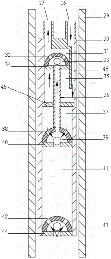
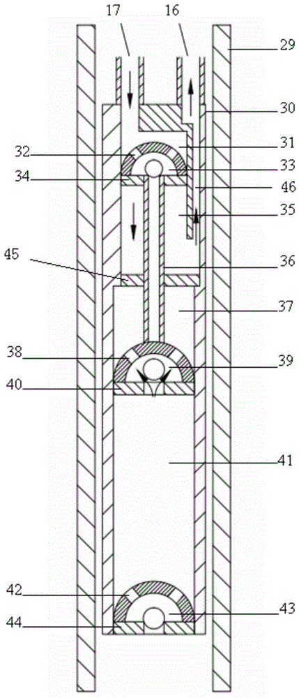
[0012] figure 1 and figure 2 It shows the downhole hydraulic piston pump of the present invention. When in use, the downhole hydraulic piston pump is lowered into the environment control in the downhole casing by using the flexible tube hydraulic transmission system, thus avoiding the trouble caused by the use of sucker rods. Various disadvantages.

[0013] The downhole hydraulic piston pump of the present invention includes a working cylinder 30 , a fixed valve 43 installed at the bottom of the working cylinder 30 , a transverse partition 45 and a double-piston structure capable of reciprocating movement in the working cylinder 30 . The transverse partition 45 is arranged on the middle and upper part of the working cylinder 30 so as to divide the working cylinder into upper and lower cavities. The upper moving valve 33 is located in the upper cavity, and the lowe...


PUM


Abstract

The invention relates to an underground hydraulic piston pump. The underground hydraulic piston pump comprises a working barrel (30), a fixed valve (43), a transverse partition (45) and a double-piston structure, wherein the fixed valve (43) is arranged on the bottom of the working barrel; the double-piston structure is positioned in inner space of the working barrel (30) and comprises an upper moving valve (33), a lower moving valve (39) and a hollow piston rod (36); and a fluid seal of the hollow piston rod (36) penetrates in the transverse partition (45), so that the upper moving valve (33) is connected with the lower moving valve (39). The underground hydraulic piston pump can descend to the tail end of a high-inclination well or a cluster well, limitation of the high-inclination well or the cluster well on the well descending depth of the underground pump is relieved, the potential productivity of an oil-gas well can be improved to the great extent, the ultimate recovery factor on the development of an oil-gas filed is increased, and the production cost is reduced while the pump efficiency is improved.

Description

technical field [0001] The invention mainly relates to a pumping system for lifting liquid in the production process of an oil and gas field, in particular to a downhole hydraulic piston pump using high-pressure liquid as a power medium. technical background [0002] In oil and gas production, the conventional piston pump is the most commonly used pumping system, but the outstanding defect of this system is: the mutual friction between the oil rod and the tubing, which will cause the tubing to perforate (wear through) and form a short circuit of the downhole liquid channel. There are downhole accidents in which the tubing and sucker rods are broken and the production string falls into the well. In addition, the ideal working state of the rod pumping system is that the downhole pipe string is all in a vertical state, so the more inclined the wellbore, the more serious the eccentric wear of the pipe and rod during the working process. Therefore, in highly deviated wells and cl...

Claims


Application Information

Patent Timeline
IPC IPC(8): F04B47/00
Inventor 潘军里群范龙江
Owner 北京万普瑞能源技术有限公司
Why Eureka
Try Eureka