
Novel folding and cutting machine

A cutting machine and a new type of technology, applied in the field of textile machinery and equipment, can solve the problems of reduced production efficiency, large occupied area and high manufacturing cost, and achieve the effects of improving stability, speed and effect.

Inactive Publication Date: 2014-05-28
深圳市诗恩纺织品有限公司
View PDF12 Cites 9 Cited by
  • Summary
  • Abstract
  • Description
  • Claims
  • Application Information

AI Technical Summary

Problems solved by technology

[0002] The two folding rods on the existing folding machine are moved by means of chain transmission, which is prone to problems in the meshing of the chain and the sprocket, which cannot increase the transmission speed. Once the transmission speed is increased, it will easily cause problems. In the case of off-chain, it greatly affects production and requires frequent maintenance and repairs
Moreover, the existing folding machine has complicated structure, high manufacturing cost, large volume and large occupied area.
[0003] The distance between the existing two folding rods cannot be adjusted, so it cannot meet the needs of folding fabrics with a large difference in thickness, which is very inconvenient
[0004] Moreover, the existing folding machine can only fold the cloth, but cannot cut it. When the number of meters required by the customer is specified, the cloth needs to be folded for the second time for cutting, which is very troublesome and reduces the production cost. efficiency

Method used

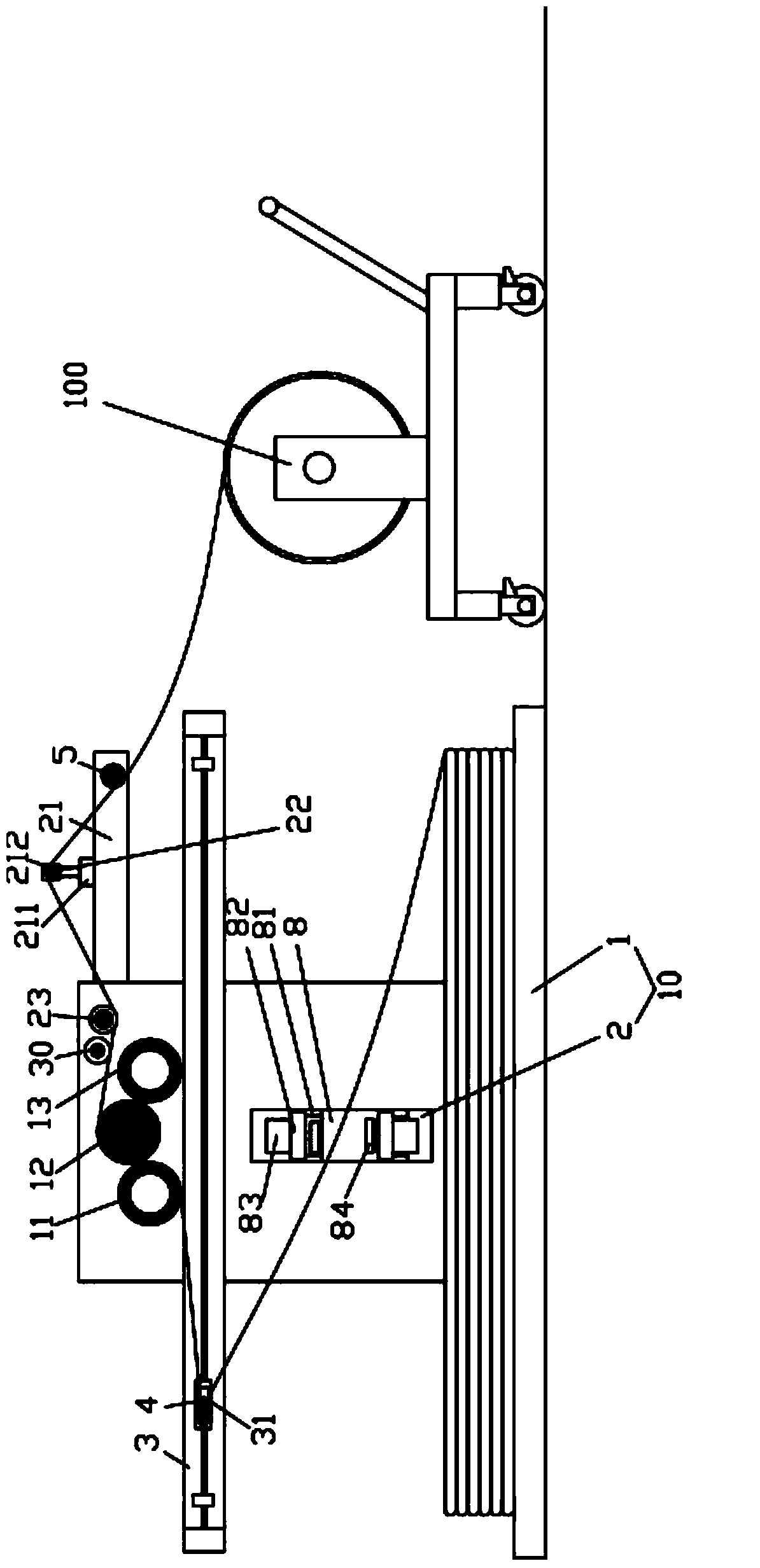
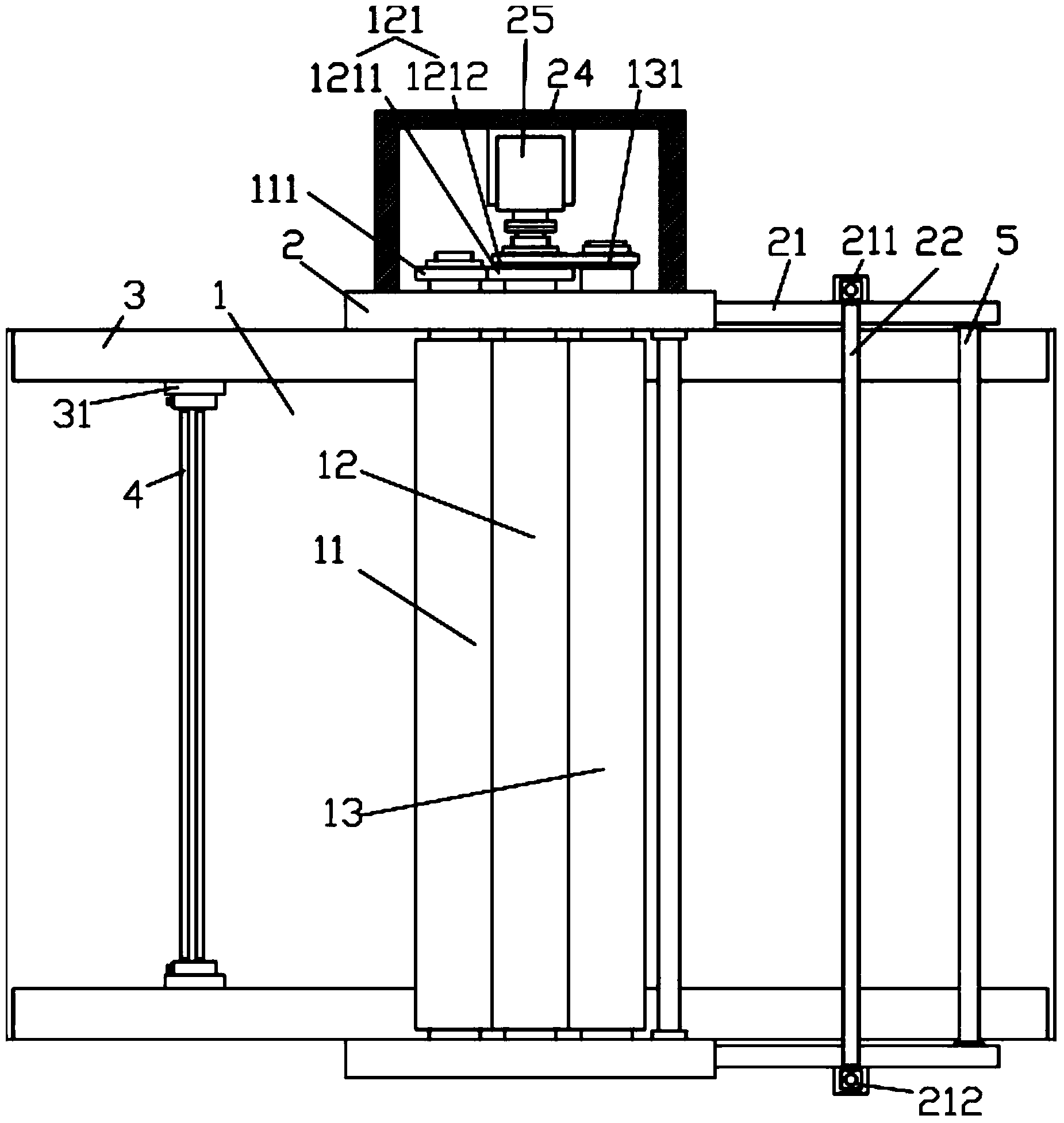
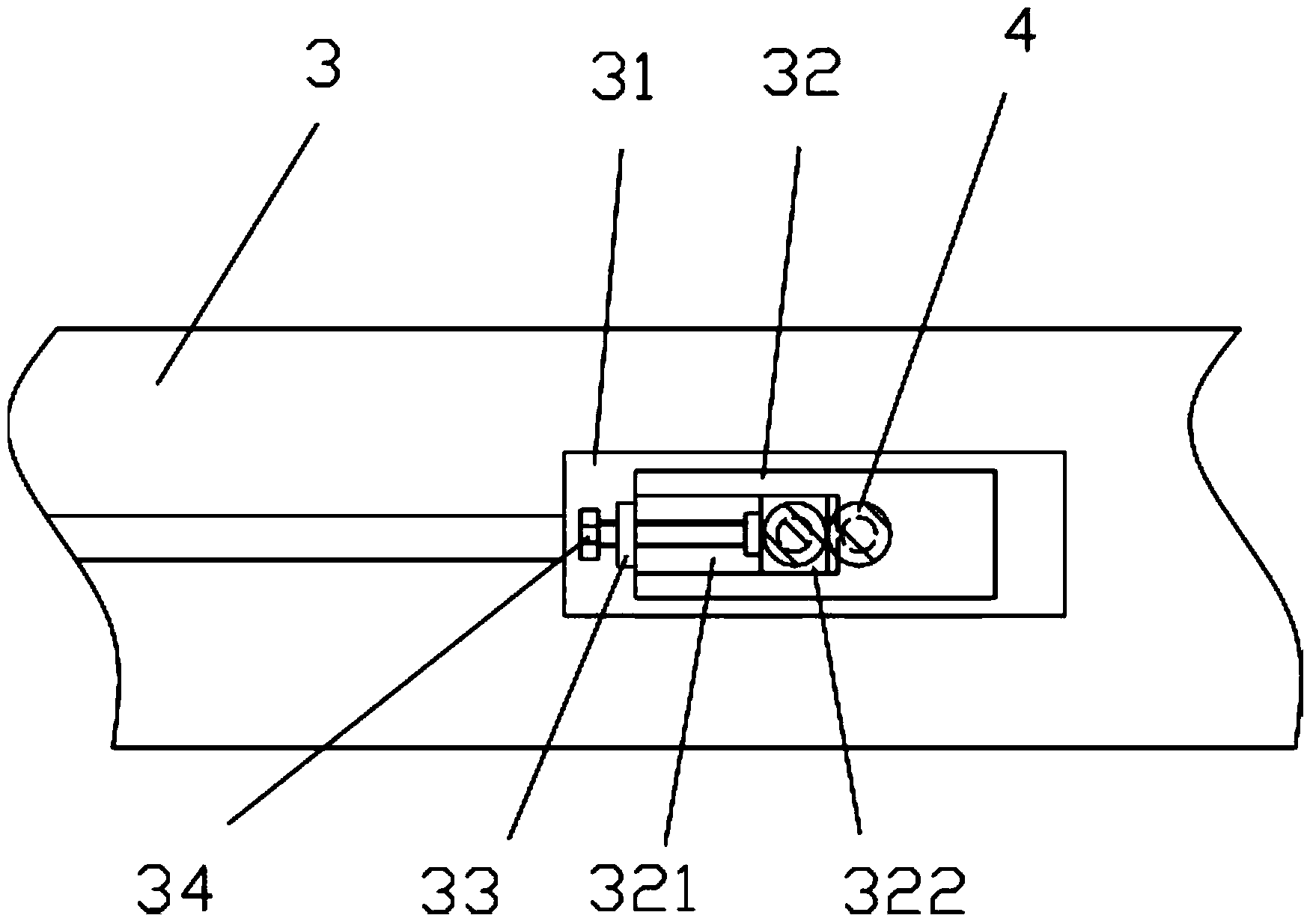

Image

  • Novel folding and cutting machine
  • Novel folding and cutting machine
  • Novel folding and cutting machine

Examples


Embodiment Construction

[0026] Examples, see Figure 1 to Figure 8 As shown, a new type of folding and cutting machine includes a frame 10, and the frame 10 includes a cloth laying board 1 at the bottom and vertical support boards 2 fixed on both sides of the cloth laying board 1, two vertical The inner side wall of the straight support plate 2 is fixed with a horizontal rodless cylinder 3, and the two ends of the two folding rods 4 are respectively arranged on the slider 31 of the rodless cylinder 3, and the two folding rods 4 are close to each other;

[0027] The two ends of the first transmission roller 11, the second transmission roller 12 and the third transmission roller 13 are respectively hinged on the top of two vertical support plates 2, and the second transmission roller 12 is connected between the first transmission roller 11 and the third transmission roller 13. between;

[0028] The right side of the top of the inner side wall of two vertical support plates 2 is hinged with middle supp...


PUM


Abstract

The invention discloses a novel folding and cutting machine which comprises a machine frame, wherein transverse rodless cylinders are fixed on the inner lateral walls of two vertical supporting plates of the machine frame, the two ends of two cloth folding rods are arranged on sliding blocks of the rodless cylinders respectively, a detection idler wheel is hinged to the vertical supporting plate on one side and a meter counter inductive head is fixed to the vertical supporting plate on the same side, an induced magnet is fixed on the back side of the detection idler wheel, and the meter counter inductive head right faces the induced magnet; a long through groove is formed in the middle of the vertical supporting plate on the left side, an upper sliding rail and a lower sliding rail are fixed on the back side of the vertical supporting plate on the left side, sliding blocks are arranged on the upper sliding rail and the lower sliding rail respectively in an inserted and sleeved mode, multiple cylinders are arranged on the sliding blocks, and pressing plates are arranged on pushing rods of the cylinders. According to the novel folding and cutting machine, the structure is simple, the folding effect is improved and folding speed is increased due to the adoption of the rodless cylinders, the distance between the two cloth folding rods can be adjusted according to the different thicknesses of cloth, meter counting and manual cutting can be conducted on folded cloth, and therefore using is convenient.

Description

Technical field: [0001] The invention relates to the technical field of textile machinery and equipment, and more specifically relates to a novel folding and cutting machine. Background technique: [0002] The two folding rods on the existing folding machine are moved by means of chain transmission, which is prone to problems in the meshing of the chain and the sprocket, which cannot increase the transmission speed. Once the transmission speed is increased, it will easily cause problems. In the case of off-chain, it greatly affects production and requires frequent maintenance and repairs. Moreover, the existing folding machine has complex structure, high manufacturing cost, large volume and large occupied area. [0003] The distance between the existing two folding rods cannot be adjusted, so it cannot meet the requirements for folding cloth with a relatively large thickness difference, which is very inconvenient. [0004] Moreover, the existing folding machine can only fo...

Claims


Application Information

Patent Timeline
Patent Type & Authority Applications(China)
IPC IPC(8): B65H45/109
Inventor 陈永林
Owner 深圳市诗恩纺织品有限公司
Learn More