A waterproof power distribution cabinet and power distribution cabinet group
A technology of power distribution cabinet group and power distribution cabinet, which is applied in the direction of substation/power distribution device shell, substation/switchgear cooling/ventilation, etc., which can solve the problems of electrical equipment not working normally and ignoring the heat dissipation of power distribution cabinets, etc.
- Summary
- Abstract
- Description
- Claims
- Application Information
AI Technical Summary
Problems solved by technology
Method used
Image

Examples
Embodiment 1
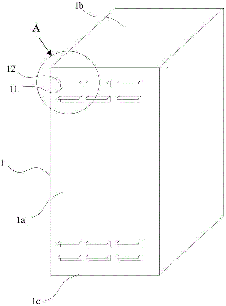
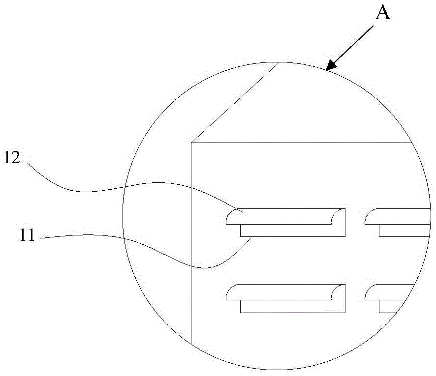
[0030] figure 1 A schematic diagram showing an embodiment of the waterproof distribution cabinet provided by the present invention, as figure 1 As shown, the cabinet body of the power distribution cabinet 1 is provided with at least one cooling hole 11, figure 2 show figure 1 Partial enlarged view at A, please also refer to figure 1 and figure 2 The upper edge of the cooling hole 11 has a water-retaining edge 12 extending outward, and the water-retaining edge 12 has a downwardly curved arc surface. The water enters the cooling holes 11 , thereby preventing water from flowing into the power distribution cabinet 1 from the cooling holes 11 . At the same time, the cooling holes 11 themselves also function to dissipate heat inside the power distribution cabinet 1 .
[0031] exist figure 1 and figure 2 In the above, the shape of the cooling hole 11 is a long strip extending in the horizontal direction. In practice, the cooling hole can also be set in other shapes, such as...
Embodiment 2
[0036] Figure 7 A schematic diagram showing an embodiment of the first power distribution cabinet group provided by the present invention, as Figure 7 As shown, the distribution cabinet group 7 includes at least two distribution cabinets 71, in Figure 7 In particular, two power distribution cabinets are used as an example for illustration, and the present invention is not limited thereto.
[0037] A cable channel shared by at least one pair of adjacent power distribution cabinets is provided between the adjacent power distribution cabinets. In practice, there are many forms of such a cable channel. For example, a cable channel cabinet may be provided between the adjacent power distribution cabinets, and the cable channel cabinet forms a cable channel. by Figure 7 As an example, a shared cable passage cabinet 73 is provided between two power distribution cabinets 71 . The cabinet space of the cabinet 73 is defined by the power distribution cabinets 71 on both sides, the...
Embodiment 3
[0041] Figure 8 A schematic diagram showing another embodiment of the first distribution cabinet group provided by the present invention, as Figure 8 As shown, the difference between the distribution cabinet group 7' and the distribution cabinet group 7 in the first embodiment mainly lies in the optimal design of the location of the busbar room.
[0042] In a common power distribution cabinet, the busbar room is set near the top of the cabinet, and equipment such as circuit breakers are installed under the busbar room. The busbar needs to be led from the busbar room to the various devices below, which makes the use of The quantity is relatively large, and the cost of the busbar is relatively high in practice, so the cost of the entire power distribution cabinet is overestimated.
[0043] This embodiment is an optimization scheme proposed after considering the above problems. See Figure 8 , the power distribution cabinet group 7' includes at least two power distribution c...
PUM
 Abstract
Description
Claims
Application Information
 - Generate Ideas
- Intellectual Property
- Life Sciences
- Materials
- Tech Scout
- Unparalleled Data Quality
- Higher Quality Content
- 60% Fewer Hallucinations
Browse by: Latest US Patents, China's latest patents, Technical Efficacy Thesaurus, Application Domain, Technology Topic, Popular Technical Reports.
© 2025 PatSnap. All rights reserved.Legal|Privacy policy|Modern Slavery Act Transparency Statement|Sitemap|About US| Contact US: help@patsnap.com