Eureka AIR delivers breakthrough ideas for toughest innovation challenges, trusted by R&D personnel around the world.

Graphic control interface design system and graphic control interface design operation method

A technology of interface design and operation method, applied in computing, program control devices, instruments, etc., can solve the problems of R&D threshold and cost increase, manpower and time cost increase, non-good designers, etc., to reduce construction and The effect of maintenance and operation cost, reduction of system integration cost, and acceleration of system development

Inactive Publication Date: 2017-03-01
CHUNGHWA TELECOM CO LTD
View PDF7 Cites 0 Cited by
  • Summary
  • Abstract
  • Description
  • Claims
  • Application Information

AI Technical Summary

Problems solved by technology

[0002] At present, the development interface technology of graphic monitoring system usually builds the monitoring system with high-level program development tools and releases it after completion. Therefore, it is impossible to edit the monitoring system online in real time, resulting in increased maintenance manpower and time costs; and the system needs auxiliary tools. Develop tools with programs, so the threshold and cost of research and development are relatively high
[0003] In addition, the complexity of the system is directly proportional to the number and scale of the controlled units. Once the number of monitoring system components increases, the error rate of the relationship between monitoring points and components will also increase significantly, and the continuous adjustment and correction will increase the development cost of the monitoring system.
It can be seen that the above-mentioned prior art still has many deficiencies, is not a good designer, and needs to be improved urgently

Method used


Image

  • Graphic control interface design system and graphic control interface design operation method
  • Graphic control interface design system and graphic control interface design operation method
  • Graphic control interface design system and graphic control interface design operation method

Examples


Embodiment Construction

[0034] In order for the examiner to understand the technical features, content and advantages of the present invention and the effects it can achieve, the present invention is hereby combined with the accompanying drawings and described in detail in the form of embodiments as follows, and the drawings used therein are, Its purpose is only for illustration and auxiliary instructions, not necessarily the true proportion and precise configuration of the present invention after implementation, so it should not be interpreted based on the proportion and configuration relationship of the attached drawings, and limit the scope of rights of the present invention in actual implementation , together first describe.

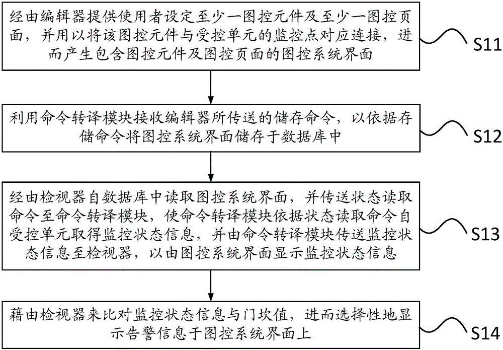
[0035] see figure 1 , which is a flow chart of the graphic control interface design operation method of the present invention. The graphical control interface design operation method is applicable to the graphical control interface design system of the present invention, a...


PUM


Abstract

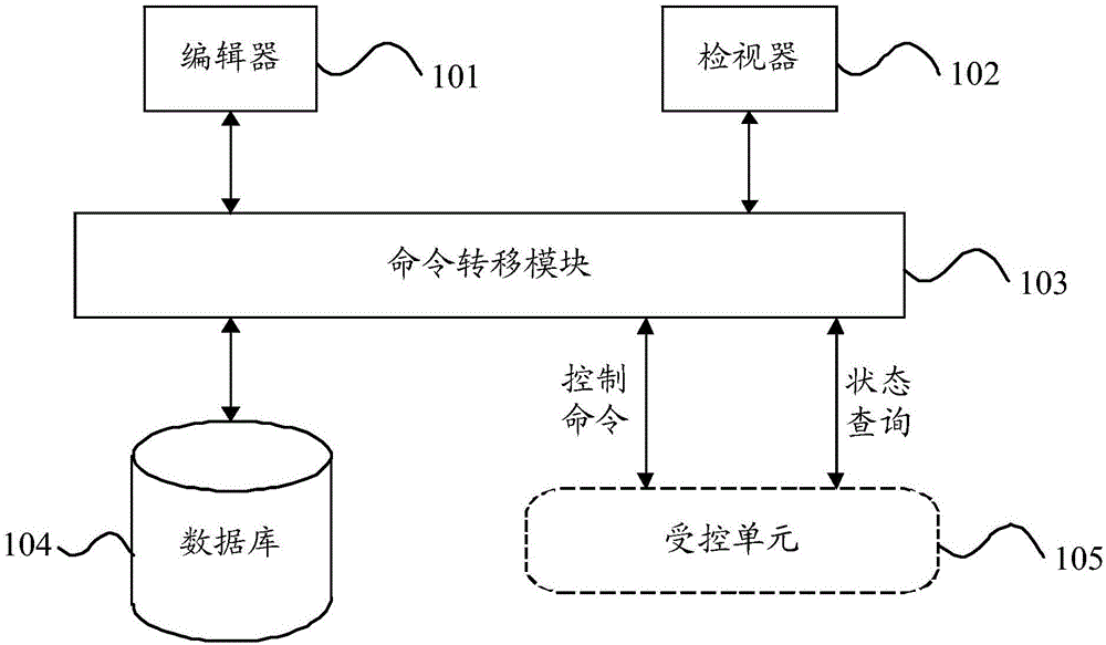
The invention discloses a graphic control interface design system and a graphic control interface design operation method thereof. The system and the method have cross-system transplantation characteristics and can design a graphic real-time monitoring system. An order translation module is responsible for translating the order content between a graphic control interface design method and an integrated heterogeneous system to be accordant to order exchange transfer regulations defined by the invention, thereby achieving the characteristics of cross-system transplantation integration. An editor performs picture editing on a monitoring system by means of a self-developed element, a system administrator capable of modifying system pictures and element parameter interfaces in real time, and a mechanism capable of establishing the corresponding relation between an element and a unit to be controlled, so that the development efficiency of the monitoring system can be improved. A monitor obtains real-time monitoring data from the unit to be controlled and displays the integral running picture after the element is updated, and then the control order to the unit to be controlled is executed by the self-developing control interface.

Description

technical field [0001] The present invention relates to a graphic-control interface design system and its method, in particular to a graphic-control interface design system and its method which can be used to design and operate a graphical real-time monitoring system with the characteristics of cross-system transplantation and integration . Background technique [0002] At present, the development interface technology of graphic monitoring system usually builds the monitoring system with high-level program development tools and releases it after completion. Therefore, it is impossible to edit the monitoring system online in real time, resulting in increased maintenance manpower and time costs; and the system needs auxiliary tools. Develop tools with programs, so the development threshold and cost are relatively high. [0003] In addition, the complexity of the system is directly proportional to the number and scale of the controlled units. Once the number of monitoring syst...

Claims


Application Information

Patent Timeline
Patent Type & Authority Patents(China)
IPC IPC(8): G06F9/44G06F3/0481
Inventor 蔡文贤曾焕然陈素莹
Owner CHUNGHWA TELECOM CO LTD
Why Eureka
Eureka Blog
Learn More