
Test method of main transformer CT (Current Transformer)

A technology of current transformer and test method, which is applied in the direction of instruments, measuring electrical variables, measuring devices, etc., can solve the problems of small secondary current of light-load equipment, unable to carry out, load phase test, unable to put into operation in time, etc., to improve work efficiency. Efficiency and inspection quality, the effect of reliable operation

Inactive Publication Date: 2014-05-21
STATE GRID CORP OF CHINA +1
View PDF4 Cites 8 Cited by
  • Summary
  • Abstract
  • Description
  • Claims
  • Application Information

AI Technical Summary

Problems solved by technology

[0003] The present invention is to provide a test method for the current transformer of the main transformer, which solves the problem that the load phase test cannot be carried out due to the too small secondary current of the light-load equipment after power transmission, so that it cannot be put into operation in time

Method used


Image

  • Test method of main transformer CT (Current Transformer)

Examples


Embodiment Construction

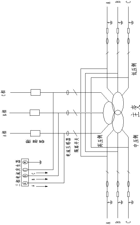
[0009] As shown in the figure, the steps of the present invention are as follows:

[0010] 1. When the current transformer carries all the secondary circuit current, use lead wires to connect the three phases of the high voltage side, medium voltage side and low voltage side of the main transformer respectively, cross the transformer, close the disconnect switch on the high voltage side and the open circuit on the other two sides On the high voltage side current transformer side of unsuitable circuit breaker and grounding isolating switch, the three-phase current is added through the three-phase current generator, so that the current flows through the current transformers on the three sides of the transformer, and the three-phase current is simulated when the transformer is in normal operation. side load current condition;

[0011] 2. The current value, phase and differential current on each side are detected at the differential protection device of the main transformer. If th...


PUM


Abstract

The invention discloses a test method of a main transformer CT (Current Transformer). The test method comprises the steps of: in the case that the current transformers have all secondary loop current, leads are used for respectively connecting the high-voltage side, the middle-voltage side and the low-voltage side of the main transformer, and stride over the transformer; an isolation switch at one side and a breaker and an earthing isolation switch at the other two sides are closed; three-phase current is applied to the current transformer side of the side with the unclosed breaker and earthing isolation switch, so that the current flows through the current transformers at three sides of the transformer so as to simulate load current states at the three sides when the transformer operates normally; the current value, phase and differential current of each side are detected at the differential protection device for the main transformer, if the differential current is equal to 0, the ratio of transformation, the polarity and the wiring of the differential loop of each current transformer are correct. According to the test method of the main transformer CT, the correctness of the current value, phase and differential current of each main transformer CT can be simultaneously tested, so that the work efficiency and test quality are improved, and the electrical device is ensured to operate reliably.

Description

technical field [0001] The invention relates to a test method for a main transformer current transformer. Background technique [0002] The substation is an important hub of the high-voltage power grid, and the current transformer is an essential primary equipment in the substation. The conventional current transformer converts the primary current with a large value into a secondary current with a small value through the principle of electromagnetic induction, which is used to control Primary equipment for protection, measurement, metering, etc. In the process of operation, for the safety of the equipment, it is necessary to prevent the secondary open circuit of the current transformer, and the transformation ratio, 10% error, and polarity of the current transformer play an important role in the correct realization of functions such as protection, protection, measurement, and metering. The primary current inspection of the main transformer current transformer is mainly to c...

Claims


Application Information

Patent Timeline
IPC IPC(8): G01R35/02
Inventor 李云陟袁泉张文力赵阳王海洋
Owner STATE GRID CORP OF CHINA
Learn More