VAV ventilation system

A ventilation system and variable air volume technology, applied in the field of ventilation systems, can solve the problem of difficulty in ensuring stable air supply from ventilation branch pipes, difficulty in effectively responding to pressure changes in main ventilation pipes with a single static pressure sensor, and difficulty in determining the proper position of a single static pressure sensor, etc. question

Active Publication Date: 2019-04-26
INST OF ENG DESIGN THE SECOND ARTILLERY FORCE OF THE PLA
View PDF5 Cites 0 Cited by
  • Summary
  • Abstract
  • Description
  • Claims
  • Application Information

AI Technical Summary

Problems solved by technology

[0002] The variable air volume ventilation technology currently used in various building ventilation and air conditioning systems usually includes total frequency conversion fans, fan frequency converters, ventilation main pipes, multi-channel ventilation branch pipes and a single static pressure sensor. Because it is difficult to determine the appropriate position of a single static pressure sensor, When the opening number of each ventilation branch pipe changes, it is difficult for a single static pressure sensor to effectively reflect the pressure change value in the main ventilation pipe, so it is difficult to ensure the stable air supply of each ventilation branch pipe

Method used


Image

  • VAV ventilation system

Examples


Embodiment 1

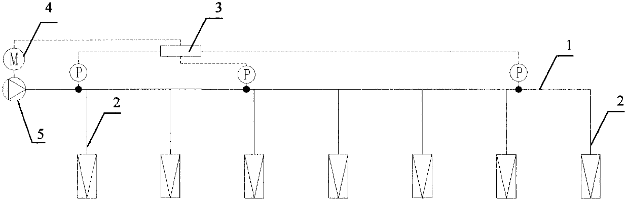
[0010] Embodiment 1: see attached figure 1 , a variable air volume ventilation system, comprising: a main ventilation pipe 1 and a multi-channel ventilation branch pipe 2, characterized in that it also includes: a plurality of static pressure sensors P, a PLC controller 3, a fan frequency converter 4 and a total frequency conversion fan 5;

[0011] The plurality of static pressure sensors P are arranged at different positions in the main ventilation pipe 1, and convert the real-time static pressure value and pressure distribution in the main ventilation pipe 1 into electrical signals;

[0012] The PLC controller 3 receives the electrical signals transmitted by the plurality of static pressure sensors P, and after weighted calculation and comparison with the set pressure value, sends a corresponding frequency conversion command to the fan frequency converter 4;

[0013] The fan frequency converter 4 changes the frequency according to the frequency conversion command issued by t...

Embodiment 2

[0014] Embodiment 2: The variable air volume ventilation system as described in Embodiment 1, when the number of the ventilation branch pipes 2 is ≤ 4, the static pressure sensor P is 2; when the number of the ventilation branch pipes 2 is ≥ 5, the There are 3 or more static pressure sensors P, one of which is arranged in front of the first and the last ventilation branch pipe 2 respectively.

Embodiment 3

[0015] Embodiment 3: The variable air volume ventilation system as described in Embodiment 1 or 2 is characterized in that: the weight distribution of the weighted calculation is: when there are 2 static pressure sensors P, at the near end of the total frequency conversion fan 5 0.35, 0.65 at the far end; when there are 3 static pressure sensors P, the near end of the total frequency conversion fan 5 is 0.2, the middle end is 0.3, and the far end is 0.5.


PUM


Abstract

The invention belongs to building ventilating air conditioner equipment and particularly relates to a variable-air-volume ventilating system. According to the technical scheme, the variable-air-volume ventilating system comprises a ventilating main pipe (1) and a plurality of ventilating branch pipes (2) and is characterized in that the variable-air-volume ventilating system further comprises a plurality of static-pressure transducers (P), a PLC (3), a draught fan frequency converter (4) and a total variable-frequency draught fan (5). A plurality of real-time static pressure values of the interior of the ventilating main pipe are subjected to weighted average calculation through the PLC, the weighting coefficient of each static pressure value is flexibly adjusted according to the distances between ventilating branch paths and resistance of each ventilating branch pipe, a final pressure calculation value serves as the pressure signal input value of the total variable-frequency draught fan, air volume equipments of each ventilating branch pipe are met in real time, and an energy saving effect is achieved.

Description

technical field [0001] The invention belongs to building ventilation and air conditioning equipment, in particular to a ventilation system. Background technique [0002] The variable air volume ventilation technology currently used in various building ventilation and air conditioning systems usually includes total frequency conversion fans, fan frequency converters, ventilation main pipes, multi-channel ventilation branch pipes and a single static pressure sensor. Because it is difficult to determine the appropriate position of a single static pressure sensor, When the opening number of each ventilation branch pipe changes, it is difficult for a single static pressure sensor to effectively reflect the pressure change value in the ventilation main pipe, so it is difficult to ensure the stable air supply of each ventilation branch pipe. Contents of the invention [0003] The purpose of the present invention is to provide a ventilation system that can adapt to changes in the ...

Claims


Application Information

Patent Timeline
Patent Type & Authority Patents(China)
IPC IPC(8): F24F11/89F24F11/88
Inventor 苏辉张晨峰方仲元涂江峰张翔邵青文
Owner INST OF ENG DESIGN THE SECOND ARTILLERY FORCE OF THE PLA
Why Eureka
Try Eureka