a wind guide mechanism

A technology of air guiding mechanism and connecting rod mechanism, which is applied in mechanical equipment, space heating and ventilation details, household heating, etc., can solve problems such as loss, prolong product development cycle, long development cycle, etc., and meet the requirement of ensuring air volume Effect

Active Publication Date: 2018-08-10
O&C ELECTRIC TECHN CO LTD
View PDF7 Cites 0 Cited by
  • Summary
  • Abstract
  • Description
  • Claims
  • Application Information

AI Technical Summary

Problems solved by technology

[0003] Under the existing technical conditions, the air volume of each air path is distributed through the design of the internal structure based on experience and some rough calculations. This product development model has a long development cycle, and the risk of air volume distribution failing to achieve the expected effect It is also relatively large, and for large and complex structural parts, once they are made into products, it is very difficult to rectify them, and even cause great losses due to scrapping, prolonging the product development cycle

Method used


Image

  • a wind guide mechanism

Examples


Embodiment Construction

[0017] In order to make the object, technical solution and advantages of the present invention clearer, the present invention will be described in further detail below in conjunction with specific embodiments and with reference to the accompanying drawings.

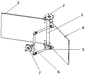
[0018] In the air path with centralized air supply and multi-channel split flow, the air supply outlet and each branch branch are usually distributed asymmetrically. In order to prevent the wind from mainly flowing away from the branch near the air inlet, it is necessary to distribute each Air volume on branch road. At the same time, due to different air supply requirements, the specifications of the air outlets are different, but the air volume requirements of the same specifications are the same. Therefore, an air guide mechanism is provided at the air inlet inside the air duct to achieve a balanced distribution of air volume.

[0019] The air guiding mechanism of the present invention comprises a rotating shaft, a fix...


PUM


Abstract

The invention provides an air guiding mechanism used for an air guiding system. The air guiding mechanism comprises a rotating shaft, a fixed diversion plate, a movable diversion plate and a connection rod mechanism, wherein the rotating shaft is fixed in an air path in the vertical direction; one side of the fixed diversion plate and one side of the movable diversion plate are hinged with the rotating shaft as a hinged shaft; the fixed end of the connection rod mechanism is hinged to the movable diversion plate. The connection rod mechanism is used for driving the movable diversion plate to rotate so that the included angle between the movable diversion plate and the fixed diversion plate can be changed, then the distribution of air volume in the air path can be changed, and the air volume demands of air paths in the system are ensured within the limited space.

Description

technical field [0001] The invention relates to the technical field of ventilation equipment, in particular to an air guide mechanism. Background technique [0002] Air supply systems are widely used in various mechanical and electrical products, central air conditioners, workshops and other equipment and buildings. And in many cases, it takes the form of centralized air supply and then split air supply. For the air supply system inside the mechanical and electrical products, the internal structure layout is generally very compact, and the space utilization rate is very high. Guarantee the air volume demand of each air path in the system. Under the condition of limited air supply, the requirements for the distribution of air flow on the air path are very high. [0003] Under the existing technical conditions, the air volume of each air path is distributed through the design of the internal structure based on experience and some rough calculations. This product development...

Claims


Application Information

Patent Timeline
Patent Type & Authority Patents(China)
IPC IPC(8): F24F13/14F24F11/74
CPCF24F11/74F24F13/1426F24F2013/1446
Inventor 刘文强王凤吾黄柱方盼盼杨斌王颖曜
Owner O&C ELECTRIC TECHN CO LTD
Why Eureka
Try Eureka