Eureka AIR delivers breakthrough ideas for toughest innovation challenges, trusted by R&D personnel around the world.

Supersonic-peed blade profile for turbine blades

A steam turbine blade, supersonic technology, applied in the direction of blade support elements, mechanical equipment, engine elements, etc., can solve the problems of blade profile loss, high Mach number at the outlet of stationary blades and moving blades, shock loss, etc. type loss, reduce shock loss, weaken the effect of interaction

Active Publication Date: 2014-05-21
HARBIN TURBINE +1
View PDF8 Cites 2 Cited by
  • Summary
  • Abstract
  • Description
  • Claims
  • Application Information

AI Technical Summary

Problems solved by technology

[0003] The invention aims to solve the problems of high Mach numbers at the exit of the stator blades and moving blades of the steam turbine unit, serious shock wave loss and blade profile loss, and further provides a supersonic blade profile for the steam turbine blade

Method used


Image

  • Supersonic-peed blade profile for turbine blades
  • Supersonic-peed blade profile for turbine blades
  • Supersonic-peed blade profile for turbine blades

Examples


specific Embodiment approach 1

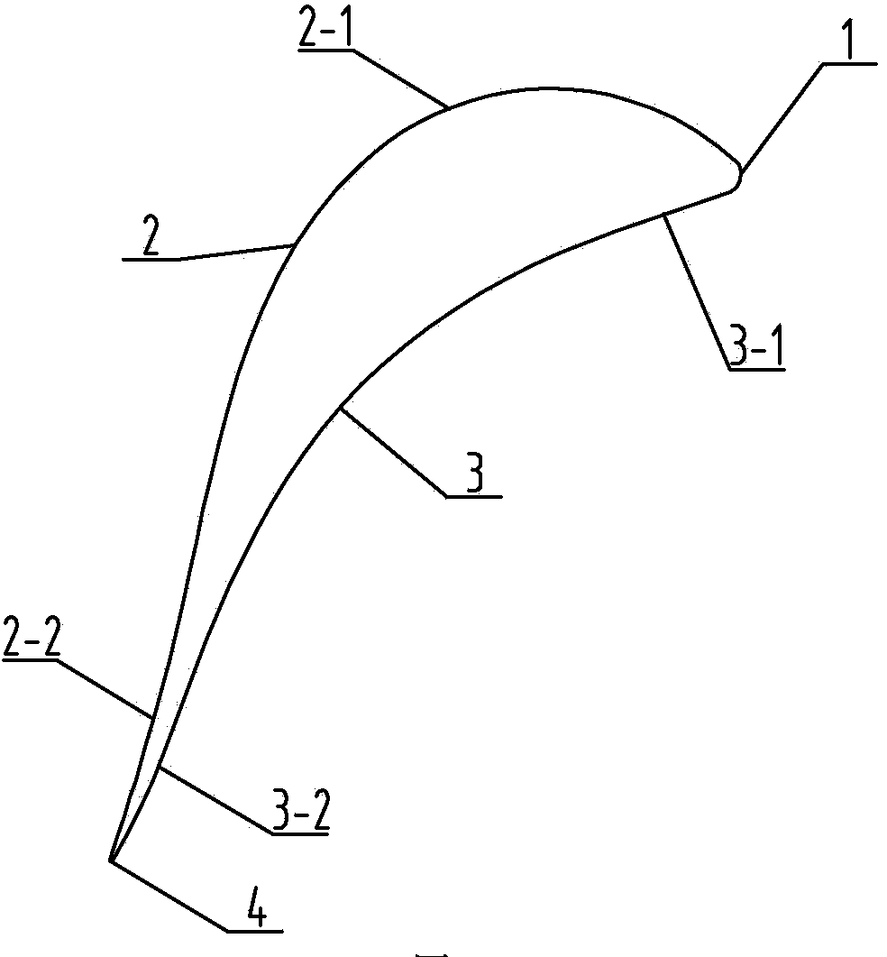
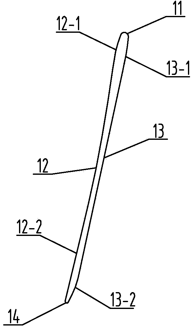
[0020] Specific implementation mode one: combine Figure 1 to Figure 6 This embodiment is described. In this embodiment, the steam turbine blade is a variable cross-section twisted blade from top to bottom. The blade is viewed from the cross section: the blade shape in the middle and lower part of the blade consists of the lower air intake edge 1, the lower back arc 2, the lower inner arc 3 and the lower inner arc. The air outlet side 4 is composed of the lower air inlet side 1, the lower back arc 2, the lower air outlet side 4 and the lower inner arc 3 connected end to end in sequence, the lower air inlet side 1 and the lower air outlet side 4 are circular arcs, and the lower air outlet side 4 The arc is smaller than the arc of the lower air intake edge 1, the side of the lower back arc 2 near the lower air intake edge 1 is an outwardly large convex arc 2-1, and the side of the lower back arc 2 near the lower air outlet edge 4 is The downward and inward small concave arc 2-2,...

specific Embodiment approach 2

[0021] Specific implementation mode two: combination Figure 5 The present embodiment will be described. The mounting angle β of the blade profile of the present embodiment is 10° to 45°. Other components and connections are the same as those in the first embodiment.

specific Embodiment approach 3

[0022] Specific implementation mode three: combination Figure 5 The present embodiment will be described. The mounting angle β of the blade profile of the present embodiment is 20°. Other components and connections are the same as those in the first embodiment.


PUM


Abstract

The invention relates to a blade profile of turbine blades, in particular to a supersonic-peed blade profile for turbine blades. The blade profile aims to solve the problem that the outlet Mach number of fixed blades and moving blades of a turboset is high. According to the cross section of the blade profile, the side, close to a lower air inlet edge, of a lower back arc is an outward large convex arc line, the side, close to a lower air outlet edge, of the lower back arc is a lower inward small concave arc line, and the outward large convex arc line is in curve transition with the lower inward small concave arc line; the side, close to the lower air inlet edge, of a lower inner arc is a lower straight line, and the side, close to the lower air outlet edge, of the lower inner arc is an outward small convex arc line; the side, close to an upper air inlet edge, of an upper back arc is a first outward small convex arc line, the side, close to an upper air outlet edge, of the upper back arc is an upper inward small concave arc line; and the first outward small convex arc line is in curve transition with the upper inward small concave arc line; the side, close to an upper air inlet edge, of an upper inner arc is a second outward small convex arc line, and the side, close to the upper air inlet edge, of the upper inner arc is a third outward small convex arc line. The blade profile is used in the turbine blades.

Description

technical field [0001] The invention relates to a blade shape of a steam turbine blade, in particular to a supersonic blade shape used for the blade of a steam turbine. Background technique [0002] The development and production of high-power steam turbine units is becoming a general direction for the development of the electric power industry. With the increase of stand-alone power, longer blades are urgently needed, especially the last-stage moving blades. Due to the high Mach number of the air outlet at the root of the stationary blade and the top of the moving blade, the design of the supersonic airfoil is urgently needed. Compared with the subsonic airfoil design, the flow field structure and loss mechanism of the supersonic airfoil have its unique characteristics. At the same time, the relative grid pitch on the top of the moving blade is large and the installation angle of the blade is small, which makes the design of the supersonic airfoil The difficulty is much h...

Claims


Application Information

Patent Timeline
Patent Type & Authority Applications(China)
IPC IPC(8): F01D5/14F01D9/02
Inventor 张秋鸿李宇峰石玉文付丽鹏薛海亮王健高永新刘云锋杨明马义良
Owner HARBIN TURBINE
Why Eureka
Eureka Blog
Learn More