an automatic lock
A technology of automatic lock and lock case, which is applied in the field of automatic lock and can solve the problems of complex structure of automatic lock
- Summary
- Abstract
- Description
- Claims
- Application Information
AI Technical Summary
Problems solved by technology
Method used
Image
Examples
Embodiment 1
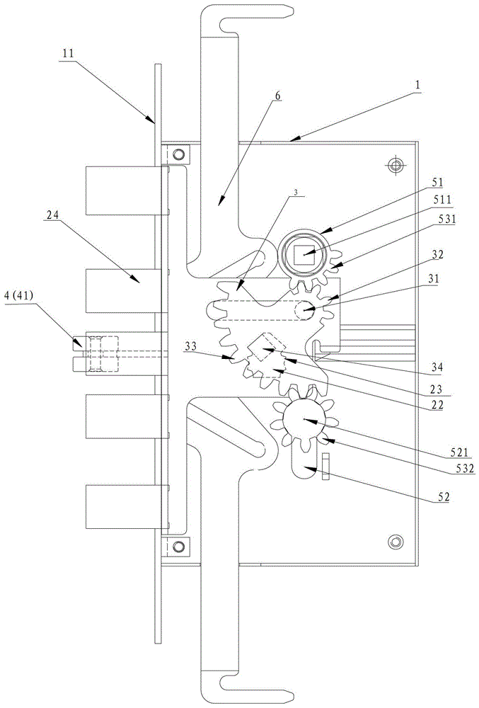
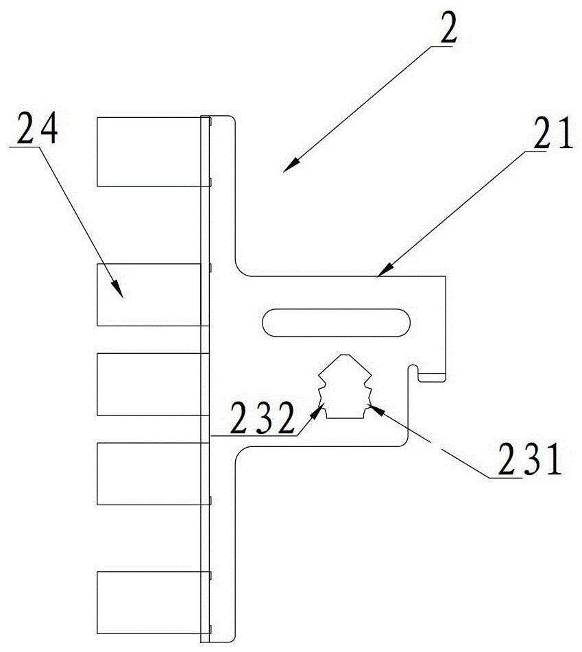
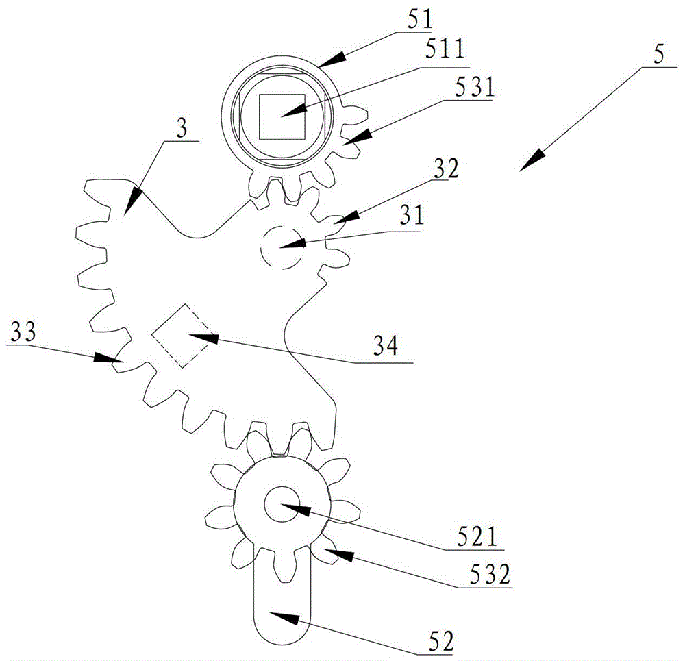
[0109] Figure 1-5 Shown is the implementation of the automatic lock described in this embodiment, including a lock case 1, a bolt member 2, a swing member 3 and a trigger assembly 4;
[0110] The lock tongue member 2 is arranged in the lock housing 1, and is limited to slide reciprocally between the lock-out terminal position and the lock-in terminal position along the lock-out direction A. In this embodiment, the lock tongue member 2 includes On the deadbolt plate 21 where the deadbolt 24 is installed, a traction groove 22 is formed on the deadbolt plate 21, and the edge of the traction groove 22 suitable for the action of the conflicting portion 34 is a guiding edge;
[0111] The swing member 3 is arranged in the lock case 1 and is rotatably mounted on the lock case 1; driven by the operating mechanism 5 to rotate around a fixed swing axis 31; between the operating mechanism 5 and the A transmission mechanism is provided between the swinging members 3, and the transmission...
Embodiment 2
[0123] Figure 6 Shown is the automatic lock described in this embodiment, including a lock case 1, a bolt member 2, a swing member 3 and a trigger assembly 4;
[0124] The lock tongue member 2 is arranged in the lock housing 1, and is limited to slide reciprocally between the lock-out terminal position and the lock-in terminal position along the lock-out direction A. In this embodiment, the lock tongue member 2 includes On the deadbolt plate 21 where the deadbolt 2 is installed, a traction groove 22 is formed on the deadbolt plate 21, and the edge of the traction groove 22 that is suitable for the action of the conflicting portion 34 is a guiding edge;
[0125] The swing member 3 is arranged in the lock case 1 and is rotatably mounted on the lock case 1; driven by the operating mechanism 5 to rotate around a fixed swing axis 31; between the operating mechanism 5 and the A transmission mechanism is provided between the swinging members 3, and the transmission mechanism includ...
Embodiment 3
[0150] Figure 17-18 Shown is the implementation of the automatic lock described in this embodiment, which includes a lock case 1, a bolt member 2, a swing member 3 and a trigger assembly 4;
[0151] The lock tongue member 2 is arranged in the lock housing 1, and is limited to slide reciprocally between the lock-out terminal position and the lock-in terminal position along the lock-out direction A. In this embodiment, the lock tongue member 2 includes On the deadbolt plate 21 where the deadbolt 24 is installed, a traction groove 22 is formed on the deadbolt plate 21, and the edge of the traction groove 22 suitable for the action of the conflicting portion 34 is a guiding edge;
[0152] The swing member 3 is arranged in the lock case 1 and is rotatably mounted on the lock case 1; driven by the operating mechanism 5, it rotates around a fixed swing shaft 31, preferably the swing shaft 31 is arranged on the The locking part 23 is located between the position of the lock-out term...
PUM
 Abstract
Description
Claims
Application Information
 - R&D
- Intellectual Property
- Life Sciences
- Materials
- Tech Scout
- Unparalleled Data Quality
- Higher Quality Content
- 60% Fewer Hallucinations
Browse by: Latest US Patents, China's latest patents, Technical Efficacy Thesaurus, Application Domain, Technology Topic, Popular Technical Reports.
© 2025 PatSnap. All rights reserved.Legal|Privacy policy|Modern Slavery Act Transparency Statement|Sitemap|About US| Contact US: help@patsnap.com


