
A mechanical arm mechanism of a linear soldering machine

A robotic arm, soldering machine technology, applied in welding equipment, auxiliary devices, metal processing and other directions, can solve the problems of difficult disassembly, difficult installation by operators, and the fixed frame cannot meet the feeding device, achieving a high degree of automation, guaranteeing Solder quality and the effect of improving processing efficiency

Active Publication Date: 2017-06-20
TANAC AUTOMATION
View PDF9 Cites 0 Cited by
  • Summary
  • Abstract
  • Description
  • Claims
  • Application Information

AI Technical Summary

Problems solved by technology

[0005] In the above-mentioned patent, the distance between the two opposite clamping devices cannot be automatically adjusted, and it is not easy to disassemble the fixture after it is fixed on it. The middle position of the machine makes it more difficult for the operator to install. At the same time, when installing the components to be soldered, the stability and firmness of the installation must also be considered, which leads to low installation efficiency of the components to be soldered.
In particular, the applicant found in the research that the soldering efficiency of the soldering machine can be improved by adding a feeding device to the soldering machine to be treated, but the fixing frame in the above patent cannot satisfy the feeding device developed by the applicant, and cannot automatically clamp and load the soldering machine. Therefore, it is urgent to develop a clamping device for components to be soldered that can improve the efficiency of soldering machining

Method used


Image

  • A mechanical arm mechanism of a linear soldering machine
  • A mechanical arm mechanism of a linear soldering machine
  • A mechanical arm mechanism of a linear soldering machine

Examples


Embodiment Construction

[0025] The present invention will be further described below in conjunction with the accompanying drawings and specific embodiments.

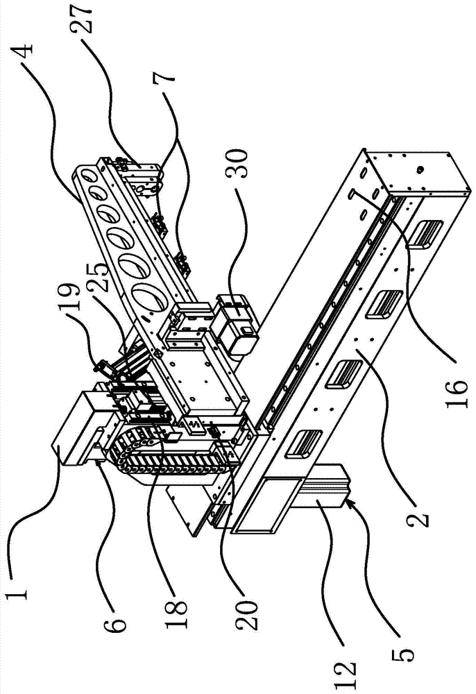
[0026] Such as figure 1 , figure 2 , image 3 As shown, the soldering machine includes a machine table, and the mechanical arm mechanism includes a support profile 2 fixed on the machine table. The support profile 2 is in the shape of a rectangular strip and has at least one guide rail along its length direction; specifically, the number of guide rails There are two guide rails 8 and 9 respectively. The first guide rail 8 and the second guide rail 9 are parallel to each other and are both arranged on the upper end surface of the support profile 2 . The mechanical arm mechanism also includes a mounting base 3 , and the lower end surface of the mounting base 3 is slidably connected to the first guide rail 8 and the second guide rail 9 . The support profile 2 is provided with a first driving device 5 capable of driving the mounting base 3 to s...


PUM


Abstract

The invention provides a mechanical arm mechanism of a linear tin soldering machine, and belongs to the technical field of welding equipment. The mechanical arm mechanism of the linear tin soldering machine solves the technical problem that the machining efficiency of a tin soldering machine is low in the prior art. The mechanical arm mechanism of the linear tin soldering machine comprises a supporting sectional material fixed to a machine table, wherein the supporting sectional material is in a rectangular strip shape, and at least one guide rail is formed in the length direction of the supporting sectional material. The mechanical arm mechanism of the linear tin soldering machine is characterized by further comprising an installation base and a mechanical arm, the installation base is connected to the guide rail in a sliding mode, the supporting sectional material is provided with a first drive device capable of driving the installation base to slide in the length direction of the guide rail, the mechanical arm is arranged in the horizontal direction, the installation base is provided with a third drive device capable of driving the mechanical arm to ascend and descend in the vertical direction, and the mechanical arm is provided with at least one pneumatic finger used for clamping and holding smelting equipment. The mechanical arm mechanism of the linear tin soldering machine has the advantages that the machining efficiency of the tin soldering machine is improved and the running stability is good.

Description

technical field [0001] The invention belongs to the technical field of welding equipment, and relates to a mechanical arm mechanism of a linear soldering machine. Background technique [0002] In the field of electronic product processing, various processing equipment are often used, and soldering machine is one of the more important equipment. Soldering machines mainly include immersion soldering machines and wave soldering machines. In the past, the soldering operation of the immersion soldering machine was mainly done manually, and it was difficult to guarantee the consistency and quality of the processing technology. [0003] Through continuous in-depth development and exploration, many manufacturers and researchers at home and abroad have developed some immersion soldering machines with a high degree of automation. The main steps are as follows: the manipulator grabs the components to be welded——soaking flux——drying——welding. [0004] Chinese patent CN 102357700A dis...

Claims


Application Information

Patent Timeline
Patent Type & Authority Patents(China)
IPC IPC(8): B23K3/00B23K3/08B23K1/08
CPCB23K1/08B23K3/00B23K3/08
Inventor 钱承林洪雪玉赵威
Owner TANAC AUTOMATION
Learn More