Spring grinding mechanism

A technology of grinding and combined mechanism, which is applied to the parts of grinding machine tools, machine tools suitable for grinding workpiece planes, grinding workpiece supports, etc. It can solve the trouble of adjusting bearing interference, affect the vertical accuracy of springs, and affect the Grinding accuracy and other issues, to achieve the effect of improving grinding accuracy and stability, high production efficiency, and low grinding cost

Active Publication Date: 2014-05-14
SHAOXING JIADU SPRING MACHINE
View PDF9 Cites 4 Cited by
  • Summary
  • Abstract
  • Description
  • Claims
  • Application Information

AI Technical Summary

Problems solved by technology

Therefore, this produces three consequences: 1), only about 17% of the whole plate spring is ground on the grinding wheel plane at the same time, and the production efficiency is low
2) The grinding amount of each spring is only 17% of the downward movement of the grinding wheel on one rotation of the grinding disc, and there is still 83% of the moving amount. The spring is actually outside the grinding wheel and has not been ground, which is unreasonable. An unreasonable consequence is that because of the sudden grinding amount at point a of the grinding wheel is large, point a wears quickly, point b wears slowly, and point c basically does not participate in grinding
Therefore, the final shape of the end face of the grinding wheel becomes a truncated cone, such as image 3 , which seriously affects the vertical accuracy of spring grinding
3) Because when the two grinding wheels are grinding, only the position that coincides with the grinding disc is stressed, and the grinding amount at point a of the grinding wheel is large, that is, the main grinding force is at this place, and the axial component of the above-mentioned grinding force is combined. Therefore, the grinding wheel shaft and the grinding wheel disc have to bear a large bending moment, resulting in a large geometric deformation, which is more obvious for heavy grinding springs, which seriously affects the spring grinding accuracy
[0007] Second, due to the unevenness of the grinding wheel during grinding, the end face of the spring is actually a plane that is not perpendicular to the axis of the spring, so the spring cannot rotate during the entire grinding process from point a to point c, so the precision of the spring after grinding is not high
This is not only difficult to find such a mechanic, but also very troublesome to adjust the interference of the bearing

Method used


Image

  • Spring grinding mechanism
  • Spring grinding mechanism
  • Spring grinding mechanism

Examples


Embodiment Construction

[0043] The following combined with the attachment and the specific embodiments further explained the present invention.

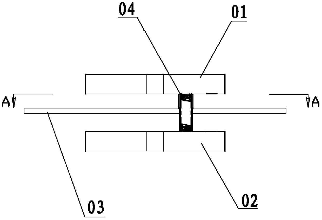
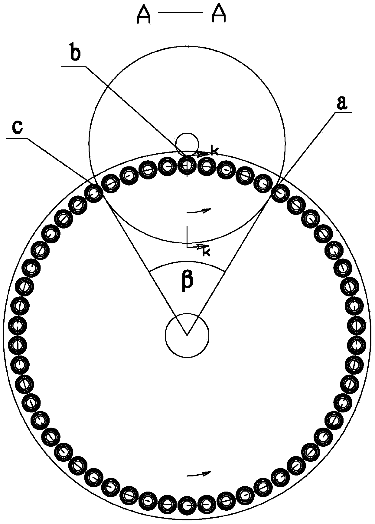
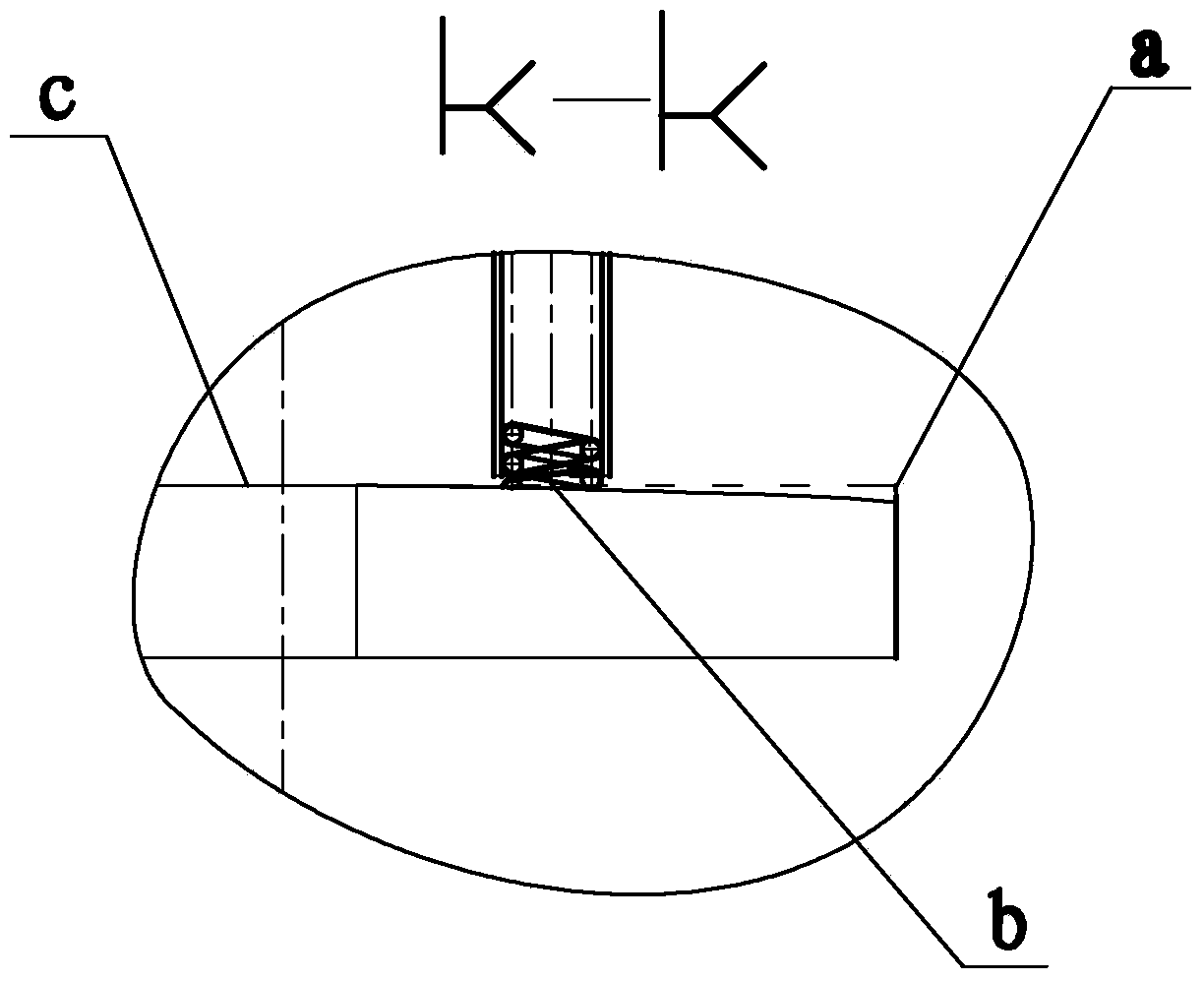
[0044] As shown in the figure, a spring grinding method and institutions revealed by the present invention, including the sand wheel 1, the lower sand wheel 2.In the example, the upper sand wheel 1 is selected as an integrated structure. The lower sand wheel 2 consists of the inner sand wheel 21 and the outer sand wheel 24. The outer diameter size of the inner sand wheel is slightly smaller than the outer sand wheel 24 inner diameter.The inner sand wheel 21 is the opposite of the rotation direction of the outer sand wheel 24. The outer sand wheel 24 is the same as the rotation direction of the upper wheel 1.The tray is installed in the inner hole to hold the spring when the spring in and out of the two sand wheels.

[0045] The grinding plate 3 is installed on the connecting rod of the swing mobile group 5, and the springs are installed on the grinding plate 3....


PUM


Abstract

The invention relates to the field of spring grinding, in particular to spring grinding mechanism. The spring grinding mechanism comprises an upper grinding wheel, a lower grinding wheel and a grinding disc. The grinding disc is located between the upper grinding wheel and the lower grinding wheel. The upper grinding wheel or the lower grinding wheel comprises an inner grinding wheel and an outer grinding wheel, wherein the inner grinding wheel sleeves the outer grinding wheel, the inner grinding wheel or the outer grinding wheel is driven by a transmission mechanism, and the rotation directions of the inner grinding wheel and the outer grinding wheel are opposite. By the arrangement, a spring is ground under self-rotation, and the quality and yield of ground springs can be increased. In addition, the spring grinding mechanism is energy saving, environmental friendly, low in grinding cost, good in stress performance, long in mechanism precision retaining ability and good in stability.

Description

Technical field [0001] [0002] The invention involves the field of spring grinding, which refers to a spring grinding mechanism. [0003] Background technique [0004] At present, the opinions of the Basic Opinion of the two -terminal grinding spring machine of the CNC springs are figure 1 As well as figure 2 , This structure is the upper and lower sand wheel 02, the upper wheel 01 can move up and down, the two sand wheels are set on the surface of the spring 04 grinding plate 03, the grinding plate 03 set a shaft rotation, the basic working principle is: grinding plate 03 fixed axis rotation, grinding discThe spring 04 on the 03 is driven by the grinding plate 03. From point A enter the two sand wheel end surface, pass through point B to point C, come out from the end surface of the two sand wheels, the spring 04 continues to be rotated by the grinding plate 03, and passes from point C.Point D reaches point A again. In this way, the spring 04 was grinded 03 to drive the entire ...

Claims


Application Information

Patent Timeline
Patent Type & Authority Applications(China)
IPC IPC(8): B24B19/00
CPCB24B7/167B24B7/17B24B41/04B24B41/047B24B41/067
Inventor 俞家林俞度黄花丽
Owner SHAOXING JIADU SPRING MACHINE
Why Eureka
Try Eureka