
Correction device and correction method for geometric position of cone beam CT system

A correction device and cone beam technology, applied in the field of biomedical imaging, can solve problems such as precision interference, and achieve the effect of fast and accurate geometric correction

Active Publication Date: 2014-05-14
北京锐视康科技发展有限公司
View PDF7 Cites 14 Cited by
  • Summary
  • Abstract
  • Description
  • Claims
  • Application Information

AI Technical Summary

Problems solved by technology

However, the accuracy of these two methods is disturbed by many factors, such as the processing accuracy of the calibration phantom, the measurement accuracy of the relative position between steel balls, etc.

Method used


Image

  • Correction device and correction method for geometric position of cone beam CT system
  • Correction device and correction method for geometric position of cone beam CT system
  • Correction device and correction method for geometric position of cone beam CT system

Examples


Embodiment Construction

[0046] In the following, the present invention will be further described through embodiments with reference to the accompanying drawings.

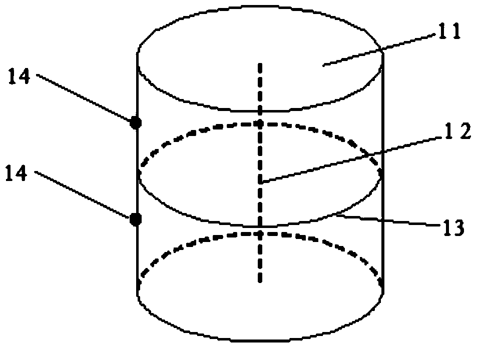
[0047] Such as figure 1 As shown, the geometric position correction device of the cone beam CT system of this embodiment includes: a support body 11, a vertical rod 12, a horizontal ring 13 and a positioning bead 14. Among them, the vertical rod 12, the horizontal ring 13 and the positioning bead 14 are all Fixed on the support 11; the points on the horizontal ring 13 are located in the same plane; the vertical rod 12 is perpendicular to the plane where the horizontal ring 13 is located; the vertical rod 12 is located at the center of the horizontal ring 13, and the horizontal ring 13 is about the vertical rod 12 is symmetrical in the center; two positioning beads 14 are respectively located on both sides of the horizontal ring 13 in a direction parallel to the vertical rod 12, and the distances to the horizontal ring 13 are equal.

[0048] Suc...


PUM


Abstract

The invention discloses a correction device and correction method for the geometric position of a cone beam CT system. The correction device comprises a supporting body, a vertical rod, a horizontal ring and locating balls. The vertical rod, the horizontal ring and the locating balls are all fixed to the supporting body. All points on the horizontal ring are arranged in the same face. The vertical rod is perpendicular to the plane where the horizontal ring is located. The two locating balls are arranged on the two sides of the horizontal ring respectively in the direction parallel to the vertical rod, and the distances between the locating balls and the horizontal ring are equal. The geometric correction device including the vertical rod, the horizontal ring and the locating balls is adopted, the projection characteristics of corresponding points, lines and faces are observed, the size and direction of the displacement errors and the angle errors of a detector are judged, corresponding adjustment is carried out, and therefore the geometric correction of the cone beam CT system is achieved faster and more accurately. After correction is completed, a relatively precise geometric parameter value can be calculated according to imaging of one or more points in the device at different positions.

Description

Technical field [0001] The invention relates to the field of biomedical imaging, in particular to a correction device and a correction method for the geometric position of a cone beam CT system. Background technique [0002] The cone beam CT system uses a cone X-ray beam and a pixel detection array to perform non-destructive imaging of the measured object. The biggest feature of the cone beam CT system is the extremely high spatial resolution, which can reach tens of microns. However, various artifacts will also appear in the image reconstruction, which seriously affects the quality of the reconstructed image. Among them, the mechanical geometric error of the CT system is an important factor causing artifacts. In the FDK algorithm for image reconstruction of cone-beam CT systems, the X-ray source focal point, the object's rotation center, and the detector imaging center are required to be in a straight line, and the plane of the detector pixel array is perpendicular to the stra...

Claims


Application Information

Patent Timeline
IPC IPC(8): A61B6/03
Inventor 杨昆李真曾海宁周坤黄益星吕江超
Owner 北京锐视康科技发展有限公司
Learn More