
Anti-loose structure

An anti-loosening and piston technology, applied in the direction of fluid pressure actuating devices, can solve the problem of no unified standards and regulations for anti-loosening forms, and achieve the effects of reliable anti-loosening effect, saving production costs and simple structure.

Inactive Publication Date: 2014-05-07
李一凡
View PDF0 Cites 1 Cited by
  • Summary
  • Abstract
  • Description
  • Claims
  • Application Information

AI Technical Summary

Problems solved by technology

[0002] At present, there are no uniform standards and regulations for the anti-loosening form used for hydraulic cylinder pistons or guide sleeves

Method used


Image

  • Anti-loose structure

Examples


Embodiment Construction

[0010] Below in conjunction with accompanying drawing, the present invention is described in further detail:

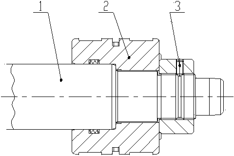
[0011] like figure 1 As shown, the present invention mainly includes a rod body 1 and a piston 2, and the rod body 1 and the piston 2 are connected by threads; a threaded hole is radially opened on the circumferential groove surface of the piston 2, and when the rod body 1 and the piston 2 are tightened on the rod body 1 The piston with the threaded hole cooperates with the rod body of the processed groove, the set screw 3 is tightened in the threaded hole, and its end is inserted into the groove.


PUM


Abstract

The invention provides an anti-loose structure, and particularly relates to a set screw radial anti-loose structure which is mainly suitable for loose prevention between various hydraulic cylinder pistons and piston rods or guide sleeves and the cylinder barrels. The anti-loose structure comprises a rod body and a piston, wherein the rod body is connected with the piston through threads, and the rod body and the piston are fixed through a screw. The piston has the tendency to rotate around the rod body, the rod body rotates along with the piston under the effect of the set screw, and thus reliable connection between the piston and the rod body is ensured. The anti-loose structure saves production cost and is simple in structure, convenient to machine and mount, reliable in anti-loose effect and high in adaptability.

Description

technical field [0001] The present invention designs an anti-loosening structure, specifically a set screw radial anti-loosening structure, which is mainly suitable for anti-loosening between pistons and piston rods of various hydraulic cylinders or between guide sleeves and cylinder barrels. Background technique [0002] At present, there is no uniform standard and regulation for the anti-loosening form used for hydraulic cylinder pistons or guide sleeves. There are glue anti-loosening, spot welding anti-loosening, and double nut anti-loosening. The quality of the anti-loosening measures directly affects the overall performance and quality of the hydraulic cylinder. In order to improve the service life and performance of the hydraulic cylinder, ensure the safety and reliability of the hydraulic cylinder. Effectively prevent thread failure such as thread loosening and leakage caused by the circumferential rotation of the piston between the rod body and the piston. Content...

Claims


Application Information

Patent Timeline
Patent Type & Authority Applications(China)
IPC IPC(8): F15B15/20
Inventor 李一凡
Owner 李一凡
Learn More