Buffer piston structure of compressor

A technology for buffering pistons and compressors, which is used in mechanical equipment, machines/engines, and liquid variable-capacity machines.

Active Publication Date: 2014-05-07
南通市红星空压机配件制造有限公司
View PDF6 Cites 3 Cited by
  • Summary
  • Abstract
  • Description
  • Claims
  • Application Information

AI Technical Summary

Problems solved by technology

[0002] In general piston air compressor equipment, the piston is directly compressed, and a large pressure is formed in an instant. The check valve on the air compressor will be opened or closed instantly, and the parts that act as the switch valve in the check valve will be subjected to instantaneous huge pressure for a long time. It is easy to be damaged, and the various conduit joints inside the equipment will also loosen and rupture due to this instantaneous huge pressure

Method used


Image

  • Buffer piston structure of compressor

Examples


Embodiment Construction

[0011] The preferred technical solutions of the present invention will be described in detail below in conjunction with the accompanying drawings.

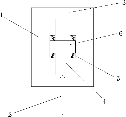
[0012] Such as figure 1 As shown, a compressor buffer piston structure of the present invention includes a piston body 1 and a crankshaft connecting rod 2 connected to the piston body 1, a buffer through hole 3 is arranged in the piston body 1, and a piston cylinder is arranged in the buffer through hole 3 4. The connecting rod 2 of the crankshaft is hinged at one end of the cylinder 4.

[0013] An inner hole structure 5 larger than the diameter of the buffer through hole 3 is set in the buffer through hole 3, and an annular step 6 that is in sealing contact with the inner wall of the inner hole structure 5 is arranged on the piston barrel 4 part in the inner hole structure 5. Spring devices connected to the inner end faces of the inner hole structure 5 are respectively arranged on the two end faces.

[0014] The length of the p...


PUM


Abstract

The invention discloses a buffer piston structure of a compressor. The buffer piston structure of the compressor comprises a piston body, and a crankshaft connecting rod connected with the piston body, wherein a buffer through hole is formed inside the piston body; a piston barrel is arranged inside the buffer through hole; the crankshaft connecting rod is hinged at one end of the piston barrel. Compared with the prior art, the buffer piston structure of the compressor has the advantages as follows: a built-in piston is arranged inside an ordinary piston, the built-in piston is hinged with a crankshaft, and the crankshaft drives the built-in piston first and then drags the external piston to move through a traction buffer device connected with the external piston, so that when a check valve of the compressor intakes and exhausts gas, a buffer effect is achieved, thereby avoiding an instantaneous relatively-high pressure and reducing wear and tear of mechanical equipment.

Description

technical field [0001] The invention relates to a buffer piston structure of a compressor. Background technique [0002] In general piston air compressor equipment, the piston is directly compressed, and a large pressure is formed in an instant. The check valve on the air compressor will be opened or closed instantly, and the parts that act as the switch valve in the check valve will be subjected to instantaneous huge pressure for a long time. It is easy to be damaged, and the various conduit joints inside the equipment will also loosen and rupture due to this instantaneous huge pressure. Contents of the invention [0003] The technical problem to be solved in the present invention is to provide a compressor buffer piston structure that can avoid damage to equipment parts due to high pressure on the piston in view of the above-mentioned deficiencies in the prior art. [0004] In order to solve the problems of the technologies described above, the technical solution ...

Claims


Application Information

Patent Timeline
IPC IPC(8): F04B39/00
Inventor 张春荣王若维袁建新王磊黄诚赵丹
Owner 南通市红星空压机配件制造有限公司
Why Eureka
Try Eureka