Optical branching unit and optical branching module thereof

A technology for optical splitting and transmission of optical fibers, applied in optical fiber transmission, fiber mechanical structure, etc., can solve problems such as difficult maintenance, messy optical splitter wires, etc., and achieve high reliability, small size, and low insertion loss.

Active Publication Date: 2014-04-30
TCL INT ELECTRICAL HUIZHOU
View PDF4 Cites 3 Cited by
  • Summary
  • Abstract
  • Description
  • Claims
  • Application Information

AI Technical Summary

Problems solved by technology

Since each optical splitter must have M input ports and N output ports, these optical fibers are connected to each other in the optical splitter, resulting in messy wires in the optical splitter and not easy to maintain

Method used


Image

  • Optical branching unit and optical branching module thereof
  • Optical branching unit and optical branching module thereof
  • Optical branching unit and optical branching module thereof

Examples


Embodiment Construction

[0031] In order to facilitate the understanding of the present invention, the present invention will be described more fully below with reference to the associated drawings. Preferred embodiments of the invention are shown in the accompanying drawings. However, the present invention can be embodied in many different forms and is not limited to the embodiments described herein. On the contrary, the purpose of providing these embodiments is to make the disclosure of the present invention more thorough and comprehensive.

[0032] It should be noted that when an element is referred to as being “fixed” to another element, it can be directly on the other element or there can also be an intervening element. When an element is referred to as being "connected to" another element, it can be directly connected to the other element or intervening elements may also be present. The terms "vertical," "horizontal," "left," "right," and similar expressions are used herein for purposes of ill...


PUM


Abstract

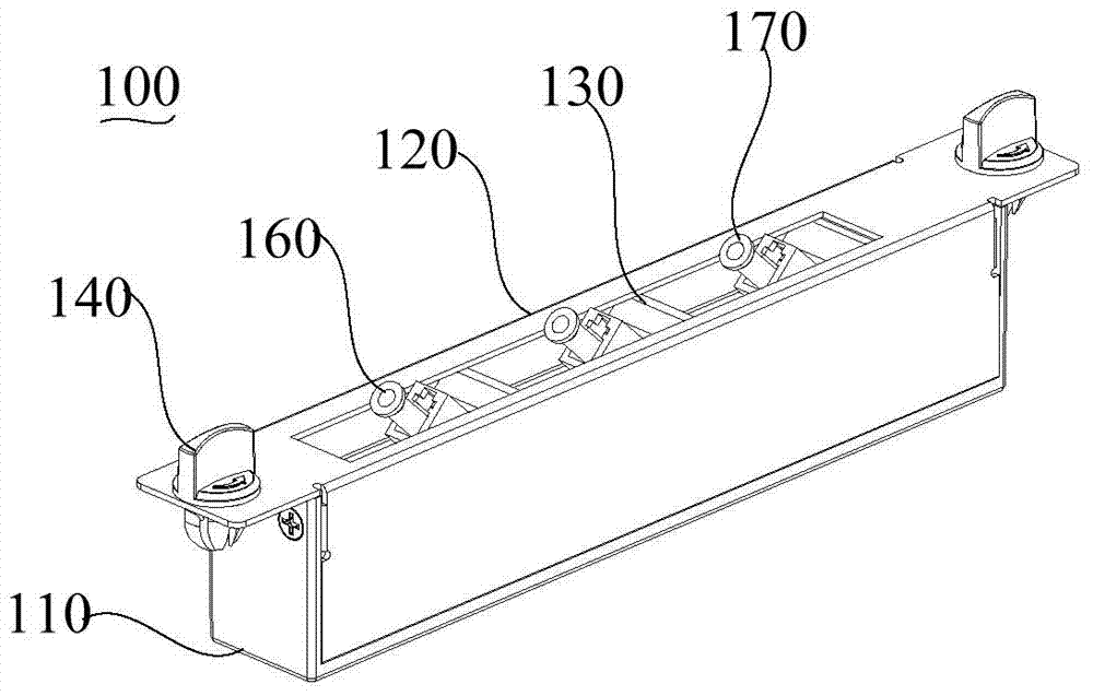
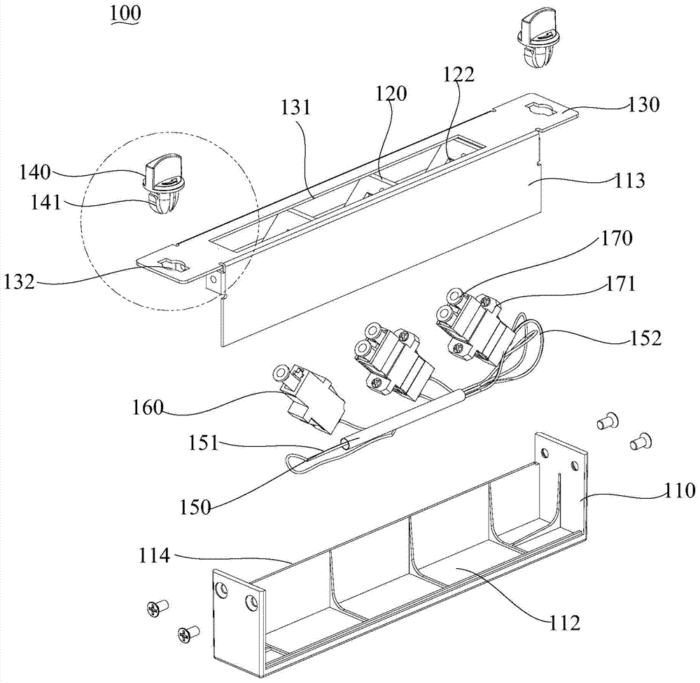
An optical branching module comprises a containing groove formed in a bottom shell. The bottom shell is covered with a panel with an opening, the opening is opposite to the containing groove, and the two ends of the panel are provided with installation holes. A transmission optical fiber is formed by multiple optical fibers in a fused biconical taper mode, the end, with one optical fiber, of the transmission optical fiber is a single-fiber end, an the other end of the transmission optical fiber is a multi-fiber end, and the multi-fiber end of the transmission optical fiber is provided with multiple optical fibers. An input end tail fiber is arranged at the single-fiber end and is in communication connection with the single-fiber end. Multiple output end tail fibers are arranged at the multi-fiber end, each output end tail fiber is in communication connection with one optical fiber at the multi-fiber end, and the output end tail fibers are contained in the containing groove. Installation knobs are contained in the installation holes and are used for being connected with external supporting objects. The transmission optical fiber of the optical branching module is of an integrated structure, complication wiring in the optical branching module can be avoided and simplicity of lines of the optical branching module is guaranteed. The invention further provides an optical branching unit.

Description

technical field [0001] The invention relates to an optical splitting device, in particular to an optical splitter and an optical splitting module thereof. Background technique [0002] The optical network system couples, branches, and distributes optical signals, which requires optical branching functional modules to realize. The optical branch function module, also known as the optical splitter, is one of the important passive devices in the optical fiber link. It is a fiber optic junction device with multiple input ports and multiple output ports. M×N is often used to represent an optical branch function. The module has M input terminals and N output terminals, and can be divided into a single-mode optical branch function module and a multi-mode fiber optical branch function module according to the transmission mode. Since each optical splitter has M input ports and N output ports, these optical fibers are connected to each other in the optical splitter, resulting in mess...

Claims


Application Information

Patent Timeline
IPC IPC(8): G02B6/44H04B10/25
Inventor 程新生吕冠文
Owner TCL INT ELECTRICAL HUIZHOU
Why Eureka
Try Eureka