
High resolution DOA estimation method and system

A high-resolution, estimation module technology, applied in the field of high-resolution DOA estimation, can solve problems such as insufficient precision, unstable estimation performance, and weak resolution ability, and achieve the effect of improving estimation accuracy and increasing degrees of freedom

Inactive Publication Date: 2014-04-30
SHENZHEN UNIV
View PDF5 Cites 27 Cited by
  • Summary
  • Abstract
  • Description
  • Claims
  • Application Information

AI Technical Summary

Problems solved by technology

These algorithms themselves can all be applied to DOA estimation in MIMO radar, and to a certain extent (such as the case where the number of transmitting antennas and receiving antennas is large and the number of sampling points is large) can provide relatively high DOA resolution, but these The disadvantages of the method mainly include: (1) The number of target sources that can be estimated is limited to a certain extent, especially when the number of transmitting antennas and receiving antennas is small, the number of target sources that can be estimated depends on the number of transmitting arrays and the number of antennas that can be shared by the receiving array, the maximum number of target sources that can be estimated by the DOA estimation algorithm of the existing method is Among them, Mt represents the number of transmitting antennas, Nr represents the number of receiving antennas; (2) When the number of transmitting antennas and receiving antennas is small, the estimated performance Unstable, the accuracy is not high enough, and the resolution capability is not strong

Method used

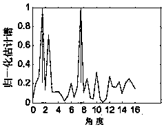
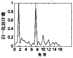
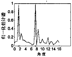

Image

  • High resolution DOA estimation method and system
  • High resolution DOA estimation method and system
  • High resolution DOA estimation method and system

Examples


Embodiment Construction

[0029] In order to make the object, technical solution and advantages of the present invention clearer, the present invention will be further described in detail below in conjunction with the accompanying drawings and embodiments. It should be understood that the specific embodiments described here are only used to explain the present invention, not to limit the present invention.

[0030] In MIMO radar, the transmitted signal can be expressed as:

[0031] x i (t)=w i (t)*s i (t) (1)

[0032] where i={1,...,M t} represents the number of transmitting antennas, w i Indicates the ith column of the Hadamard matrix, s i Indicates the i-th column of a real random matrix consisting of equiprobable distributions -1 and 1, and t represents time. The transmit waveforms in MIMO radar are orthogonal and independent to each other, so there are:

[0033] ∫ 0 T x ( t - ...


PUM


Abstract

The invention belongs to the technical field of MIMO radars, and provides a high resolution DOA estimation method and system. The method includes the following steps that all receiving antennas receive transmitting signals reflected by target sources; a receiving signal of each receiving antenna is scanned through the transmitting signals, so that the corresponding relay of each transmitting signal is obtained; the transmitting signals are adjusted according to the obtained delay, the conjugate of each adjusted transmitting signal is multiplied with the receiving signal of each antenna, and accordingly the phase positions, corresponding to all peak points, in the receiving signal of each receiving antenna are obtained; virtual expansion signals are established according to the obtained phase positions and adjusted transmitting waveform signals; novel receiving signals are formed by the virtual expansion signals and the receiving signals, the covariance and the Capon wave beams of the novel receiving signals are calculated to form coefficients, and thus DOA estimation is completed. According to the high resolution DOA estimation method and system, under the condition that antennas are not additionally arranged, estimated accuracy can be improved, and the number of target sources which can be estimated can be increased.

Description

technical field [0001] The invention belongs to the technical field of wireless communication, and in particular relates to a high-resolution DOA estimation method and system suitable for MIMO radar systems. Background technique [0002] MIMO radar uses multi-antenna technology to simultaneously transmit independent signal beams to detect targets and receive signals reflected by targets. The reflected signal carries information about the target, such as angle, distance, Doppler shift, etc., which can be extracted at the receiving end by using a matched filter method. MIMO radar can flexibly adopt the high-bandwidth, two-way digital beamforming and waveform diversity technologies of the new generation radar system. At the same time, each antenna is required to transmit mutually orthogonal signals. Space targets form space diversity, which can improve the detection ability of air targets. The characteristics of transmitted signals and the design of space diversity in MIMO ra...

Claims


Application Information

Patent Timeline
Patent Type & Authority Applications(China)
IPC IPC(8): G01S3/14G01S7/02
CPCG01S13/42G01S3/74G01S13/06
Inventor 谢宁郭伟斌王晖林晓辉曾捷
Owner SHENZHEN UNIV
Learn More