
Packless sealing proportional valve

A proportional valve, tight technology, applied in the direction of valve details, multi-way valves, valve devices, etc., can solve the problems of poor valve closing, poor flow adjustment effect, short service life, etc., to achieve convenient flow adjustment, tight closing, The effect of long service life

Inactive Publication Date: 2014-04-30
威海柳道机械有限公司
View PDF0 Cites 1 Cited by
  • Summary
  • Abstract
  • Description
  • Claims
  • Application Information

AI Technical Summary

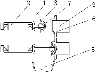
Problems solved by technology

[0002] As we all know, the valve is a common part of the pipeline. The valve is used to control the opening, closing and flow adjustment of the pipeline. At present, the valves of the raw material pipeline adopt a tight sealing method, which is composed of a valve body, a valve stem and a valve core. The valve body There is a material inlet and a material outlet on the top, the valve core is matched with the material inlet, and the valve stem is connected with the valve core to control the working state of the valve core. The cooperation between the valve core and the material inlet or material outlet is The inlet or outlet is provided with a sealing boss, and the valve core is provided with a sealing ring surface corresponding to the boss, and the sealing ring surface of the valve core is tightly pressed against the inlet or outlet through the valve stem. On the sealing boss of the valve, in order to increase its sealing effect, some gaskets are provided on the sealing ring surface. However, the discharge port is severely worn, and when it is closed, impurities are easily trapped between the valve core and the sealing surface of the feed port or discharge port, which makes it have short service life and poor flow adjustment effect. In addition, the valve core is tight The conveyed raw material is easily trapped between the sealing surface and the boss of the inlet or outlet, which makes the valve not tightly closed.

Method used


Image

  • Packless sealing proportional valve

Examples


Embodiment Construction

[0011] The present invention will be further described below in conjunction with the accompanying drawings.

[0012] As shown in the figure, a non-tight sealing proportional valve is composed of a valve body 1, a valve stem 2 and a valve core 3. The valve body 1 is provided with a feed port 4 and a discharge port 5. The valve body 1 can be There is one material inlet and two material outlets, the material outlets are matched with the valve core, the valve body 1 can also be provided with two material inlets and one material outlet, the material inlets are matched with the valve core, to Applicable to different workplaces, the valve core 3 matches the feed port 4 and the discharge port 5 with a tapered surface, the feed port 4 or the discharge port 5 is provided with a sealing boss 6, and the inner hole of the boss 6 is set There is a tapered sealing ring surface, and the tapered sealing ring surface of the valve core is matched with the tapered sealing ring surface of the inne...


PUM


Abstract

The invention relates to a valve for a pipeline, and in particular to a packless sealing proportional valve. The packless sealing proportional valve is composed of a valve body, a valve rod and a valve core, wherein a charge port and a discharge port are formed in the valve body. The packless sealing proportional valve is characterized in that the valve core is matched with the charge port and the discharge port by conical surfaces, the charge port and the discharge port are provided with sealing bosses, and conical sealing annular surfaces are arranged in the inner holes of the bosses. During the use of the packless sealing proportional valve disclosed by the invention, the charge port and the discharge port are connected with a charge tube and a discharge tube by pipeline joint parts respectively, the flow, opening and closing of the charge port and the discharge port are controlled by a valve rod regulator flow valve core and the valve core, the valve core is matched with the charge port and the discharge port by means of conical surfaces, and the application of a pressure is not required during closing. The packless sealing proportional valve has the advantages of being convenient to regulate flow, tight in closing, long in service life, and the like.

Description

technical field [0001] The invention relates to a valve for pipelines, in particular to a non-tight sealing proportional valve with good sealing effect and long service life. Background technique [0002] As we all know, the valve is a common part of the pipeline. The valve is used to control the opening, closing and flow adjustment of the pipeline. At present, the valves of the raw material pipeline adopt a tight sealing method, which is composed of a valve body, a valve stem and a valve core. The valve body There is a material inlet and a material outlet on the top, the valve core is matched with the material inlet, and the valve stem is connected with the valve core to control the working state of the valve core. The cooperation between the valve core and the material inlet or material outlet is The inlet or outlet is provided with a sealing boss, and the valve core is provided with a sealing ring surface corresponding to the boss, and the sealing ring surface of the valv...

Claims


Application Information

Patent Timeline
IPC IPC(8): F16K11/22F16K27/00
CPCF16K11/22F16K27/0263
Inventor 秀荣
Owner 威海柳道机械有限公司
Learn More