
Concrete protection pile

A protective pile and concrete technology, which is applied to sheet pile walls, buildings, and foundation structure engineering, can solve problems such as poor slope protection effect of concrete protective walls, landslides, dam breaks, and easy deviation of protective piles, so as to avoid soil erosion , Good bending resistance, good slope protection effect

Active Publication Date: 2014-04-30
李全民
View PDF5 Cites 1 Cited by
  • Summary
  • Abstract
  • Description
  • Claims
  • Application Information

AI Technical Summary

Problems solved by technology

[0002] Concrete protection piles are commonly used building materials in protection engineering. When in use, multiple protection piles are rammed into the ground to form a concrete protection wall, which is used for slope protection, embankment, soil retaining, cofferdam and other projects. The existing concrete protection piles are generally It is a non-socket connection or a U-shaped rigid socket connection. Due to the deviation during construction, there is often a gap between two adjacent protection piles without a socket connection and there is no mechanical connection between them and it is easy to shift. The U-shaped rigid socket connection is used Similarly, there is no mechanical connection between them, and it is easy to shift. Even if the gap between two adjacent protective piles is sprayed with high-pressure water and poured with concrete slurry, there will be gaps. The protection effect of the embankment is poor, and the embankment is prone to leakage, perforation, etc., and even accidents such as landslides and dam breaks

Method used


Image

  • Concrete protection pile
  • Concrete protection pile
  • Concrete protection pile

Examples


Embodiment Construction

[0013] In order to clearly illustrate the technical features of this solution, the present invention will be described in detail below through specific implementation modes and in conjunction with the accompanying drawings.

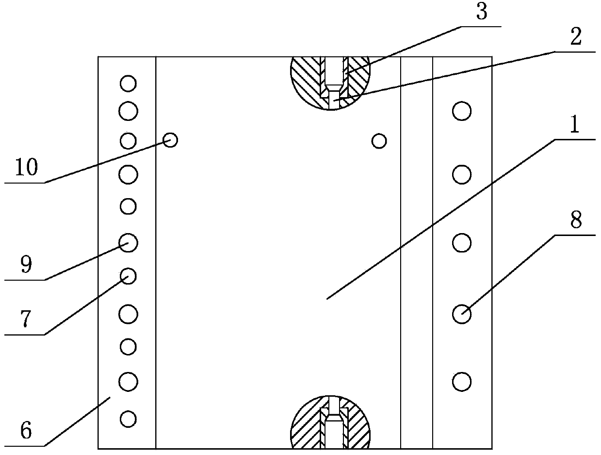
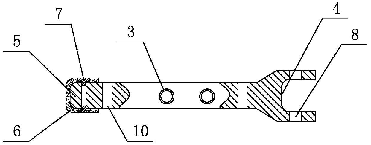
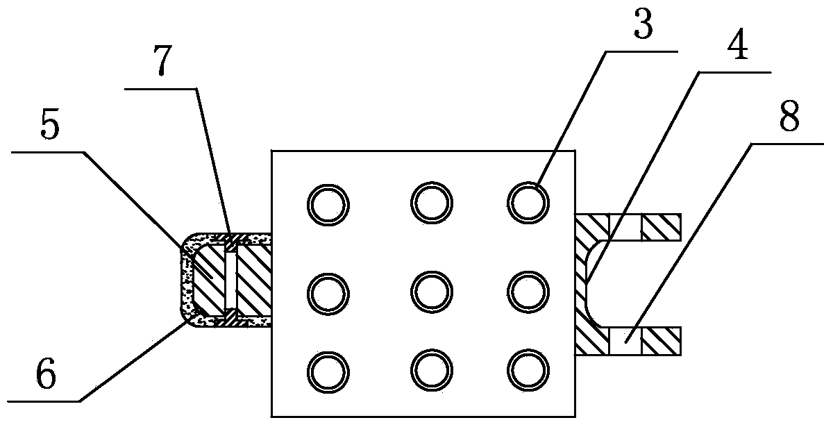
[0014] Such as Figure 1-3 Shown: a concrete protective pile, inside the pile body 1, several prestressed steel rods 2 are arranged along the vertical direction of the pile body 1, steel wire mesh is arranged on the prestressed steel rods 2, and the prestressed steel rods 2 Rebar anchor nuts 3 are respectively provided at both ends of the pile body 1, a U-shaped socket 4 is provided at one end of the pile body 1, a plug-in 5 matching with the U-shaped socket 4 is provided at the other end of the pile body 1, a flexible rubber sleeve 6 is covered and fixed on the plug-in 5 through the countersunk crab shell bolt 7, and several first bolt holes 8 are arranged symmetrically along the vertical direction on the two straight ends of the U-shaped socket 4, and t...


PUM


Abstract

The invention relates to a concrete protection pillar. Multiple prestress steel rods are arranged in a pile body in the vertical direction of the pile body. Steel wire nets are arranged on the prestress steel rods and the two ends of each prestress steel rod are provided with steel rebar anchoring nuts respectively. One end of the pillar body is provided with a U-shaped bellmouth and the other end of the pillar body is provided with an insertion part which is matched with the U-shaped bellmouth. A flexible rubber sleeve is fixed to the insertion part by means of covering of a countersunk head crab-shell-shaped bolt. By means of the technical scheme, the concrete protection pillar is reasonable in structural design. A flexible bell and spigot structure is adopted, adjacent two concrete protection pillars are tightly connected, the sealing effect is good, thus a concrete protection wall formed by the concrete protection piles in this way can stop water and mud, the slope protection effect is good, water and soil losses are avoided, the dam protecting effect is good, leakage, piercing and the like of the dam are avoided and safety of the dam is ensured.

Description

technical field [0001] The invention relates to a concrete protective pile. Background technique [0002] Concrete protection piles are commonly used building materials in protection engineering. When in use, multiple protection piles are rammed into the ground to form a concrete protection wall, which is used for slope protection, embankment, soil retaining, cofferdam and other projects. The existing concrete protection piles are generally It is a non-socket connection or a U-shaped rigid socket connection. Due to the deviation during construction, there is often a gap between two adjacent protection piles without a socket connection and there is no mechanical connection between them and it is easy to shift. The U-shaped rigid socket connection is used Similarly, there is no mechanical connection between them, and it is easy to shift. Even if the gap between two adjacent protective piles is sprayed with high-pressure water and poured with concrete slurry, there will be gaps...

Claims


Application Information

Patent Timeline
IPC IPC(8): E02D5/10E02D5/12E02D5/14
Inventor 李全民
Owner 李全民
Learn More