Conveyor

A technology of a transmission device and a conveyor belt is applied in the field of transmission appliances, which can solve the problems of increased use of personnel, low efficiency, and increased cost, and achieves the effects of good diversion effect, large transmission volume, and convenient transmission.

Inactive Publication Date: 2014-04-30
德清县凌鹰电器有限公司
View PDF5 Cites 2 Cited by
  • Summary
  • Abstract
  • Description
  • Claims
  • Application Information

AI Technical Summary

Problems solved by technology

This kind of traditional method has the following defects: first, manual operation makes the efficiency low; Some links that require assembly line operation have caused great inconvenience

Method used


Image

  • Conveyor

Examples


Embodiment Construction

[0014] Combine below figure 1 Specific examples:

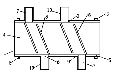
[0015] A transmission device, comprising a frame 1, the frame 1 is provided with a driving roller 2 and a driven roller 3, the driving roller 2 is connected with a motor, the driving roller 2 and the slave A conveyor belt 4 is provided on the moving roller 3, and the conveyor belt 4 is movable under the driving of the driving roller 2 and the driven roller 3. The frame 1 is provided with protective plates 5 on both sides of the conveyor belt 4 , The protective plate 5 is provided with a plurality of notches 6, and the notches 6 are connected with a plurality of shunt grooves 7, and the notches 6 are hinged with a shunt plate 8, and the shunt plate 8 can block the notch 6. , The length of the dividing plate 8 is greater than the width of the conveyor belt 4. A gap 9 is opened at the junction of the shunt groove 7 and the protective plate 5, and the other end of the shunt plate 8 can be clamped in the gap 9. Baffles 10 are provi...


PUM


Abstract

The invention belongs to the technical field of conveying devices, and particularly relates to a conveyor. The conveyor comprises a frame. A driving roller and a driven roller are arranged on the frame. The driving roller is connected with a motor. A conveying belt is arranged on the driving roller and the driven roller. Protecting plates are arranged on the frame and on two sides of the conveying belt. A plurality of notches are arranged on each protecting plate. A plurality of flow distribution grooves are connected to the notches respectively. A flow distribution plate is hinged to each notch and can block the corresponding notch. The length of each flow distribution plate is larger than the width of the conveying belt. By the conveyor, parts and finished products are enabled to be conveyed conveniently and rapidly, good flow distribution effect can be achieved, conveying quantity is large, and various different articles can be conveyed simultaneously.

Description

Technical field [0001] The invention belongs to the technical field of transmission appliances, and particularly relates to a transmission device. Background technique [0002] In the production of the factory, when many parts and some finished products need to be transported, the parts and finished products are directly placed in boxes. Then, manually or by means of transportation, the parts or finished products are transported to the place where they are needed. Such traditional methods have the following shortcomings: First, manual operation makes the efficiency low; second, personnel are required to carry during the transportation process, which increases the use of personnel and increases the cost; third, the Some links that require assembly line operation cause greater inconvenience. Summary of the invention [0003] The purpose of the present invention is to solve the above-mentioned technical problems and provide a transmission device, the technical solution of which is ...

Claims


Application Information

Patent Timeline
Patent Type & Authority Applications(China)
IPC IPC(8): B65G15/00B65G47/34
Inventor 沈苏英梅乐
Owner 德清县凌鹰电器有限公司
Why Eureka
Try Eureka