
Ultrasonic-Doppler-effect positioning puncturing device for vessel

A Doppler effect and vascular technology, applied in the field of ultrasonic Doppler effect vascular positioning puncture devices, can solve the problems of increasing patient pain and psychological burden, tissue damage, lack of puncture angle and puncture depth information, etc. Effects of pain and psychological burden

Active Publication Date: 2014-04-30
SHANTOU INST OF UITRASONIC INSTR CO LTD
View PDF5 Cites 15 Cited by
  • Summary
  • Abstract
  • Description
  • Claims
  • Application Information

AI Technical Summary

Problems solved by technology

[0003] In order to make the puncture accurate, Doppler ultrasound positioning technology is usually used at present, that is, the ultrasonic probe is used to detect the lesion position on the patient's body, and then the doctor holds a puncture device including a needle barrel and a puncture needle for puncture. During the puncture process (including needle insertion) , needle stop, needle withdrawal), only based on the doctor's feeling and experience, there is no accurate puncture angle and puncture depth information. Case
If the puncture is not in place, the purpose of inspection and sampling will not be achieved, and a new puncture will be required, which will undoubtedly increase the pain and psychological burden of the patient
Puncturing a blood vessel causes tissue damage and also requires repunching

Method used


Image

  • Ultrasonic-Doppler-effect positioning puncturing device for vessel
  • Ultrasonic-Doppler-effect positioning puncturing device for vessel
  • Ultrasonic-Doppler-effect positioning puncturing device for vessel

Examples


Embodiment Construction

[0017] Further description will be given below in conjunction with the accompanying drawings and preferred embodiments of the present invention.

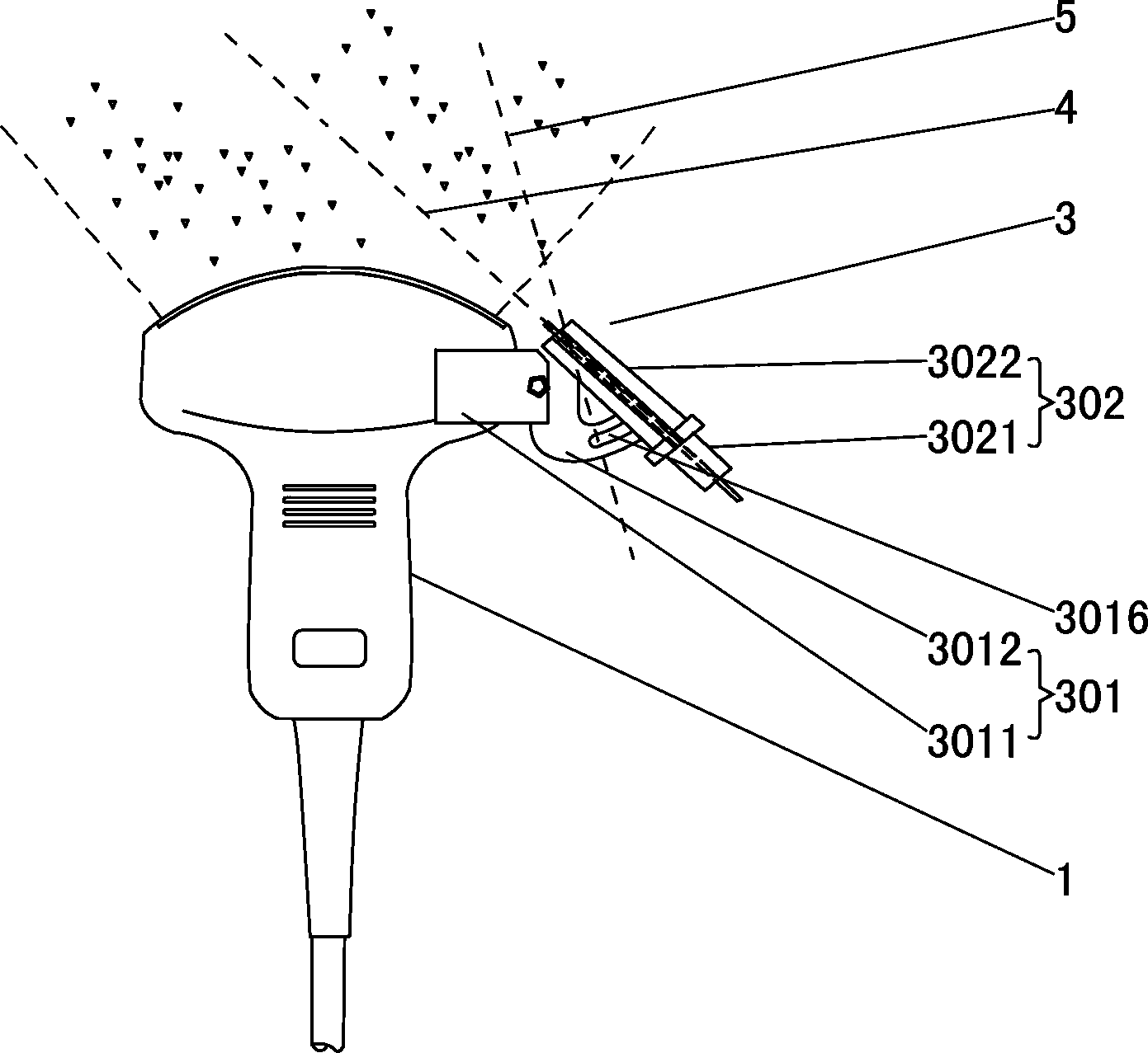
[0018] Such as figure 1 with figure 2 As shown, this ultrasonic Doppler effect vessel positioning puncture device includes an ultrasonic probe 1, a main control system 2 and a puncture device 3; the puncture device 3 includes a bracket 301, a syringe 302, a needle 303, a first encoder 304 and The second encoder 305; the bracket 301 includes a seat body 3011 and a supporting plate 3012, the seat body 3011 is installed on the supporting plate 3012, the seat body 3011 is provided with a U-shaped notch 3013, and one side of the seat body 3011 is provided with a first screw hole 3014 , the ultrasonic probe 1 is provided with a second screw hole 101, the U-shaped notch 3013 is clamped on the ultrasonic probe 1, and the screw ( figure 1 not shown), the first screw hole 3014, and the second screw hole 101 lock the base 3011 on the ultras...


PUM


Abstract

The invention relates to an ultrasonic-Doppler-effect positioning puncturing device for the vessel. The device comprises an ultrasonic probe, a main control system and a puncturing device. The puncturing device comprises a support, a needle tube, a puncturing needle, a first coder and a second coder. The support is installed on the ultrasonic probe, the front end of the needle tube is installed infront of the support in a rotatable mode, an arc-shaped groove is formed in the rear of the support, and a guide rod is arranged at the rear end of the needle tube and located in the arc-shaped groove. The first coder is installed on the side wall of the needle tube, the second coder is installed on the guide rod, and the ultrasonic probe, the first coder and the second coder are electrically connected with the main control system. Due to the fact that the first coder and the second coder are arranged, through linkage between the needle tube and the ultrasonic probe, needle insertion is guided according to a puncturing range, a puncturing thread, angle information and depth information, the puncturing angle and puncturing depth of the puncturing needle are accurately controlled, it is ensured that a needle head of the puncturing needle accurately reaches the vessel of a focus part, then puncturing work is finished in a one-off mode, and the ultrasonic-Doppler-effect positioning puncturing device is safer and more reliable.

Description

technical field [0001] The invention relates to a medical puncture device, in particular to an ultrasonic Doppler effect vessel positioning puncture device. Background technique [0002] At present, it is often necessary to puncture the lesion of the patient in medical treatment, so as to perform operations such as inspection and sampling of the lesion. [0003] In order to make the puncture accurate, Doppler ultrasound positioning technology is usually used at present, that is, the ultrasonic probe is used to detect the lesion position on the patient's body, and then the doctor holds a puncture device including a needle barrel and a puncture needle for puncture. During the puncture process (including needle insertion) , needle stop, needle withdrawal), only based on the doctor's feeling and experience, there is no accurate puncture angle and puncture depth information. Case. If the puncture is not in place, the purpose of inspection and sampling cannot be achieved, and a ...

Claims


Application Information

Patent Timeline
IPC IPC(8): A61B10/02A61B8/00
Inventor 李德来郭境峰赵榉云
Owner SHANTOU INST OF UITRASONIC INSTR CO LTD
Learn More