Intelligent lighting system based on CAN bus

A CAN bus, intelligent lighting technology, applied in the field of lighting systems, can solve problems such as inability to meet, complicated wiring, etc., to achieve the effect of intelligent lighting

Inactive Publication Date: 2014-04-23
GUANGXI UNIVERSITY OF TECHNOLOGY
View PDF2 Cites 0 Cited by
  • Summary
  • Abstract
  • Description
  • Claims
  • Application Information

AI Technical Summary

Problems solved by technology

This traditional lighting control method has simple functions and complicated wiring, which is far from meeting the requirements of today's social development.

Method used


Image

  • Intelligent lighting system based on CAN bus

Examples


Embodiment Construction

[0021] The specific implementation manner of the embodiment of the present invention is described in detail below:

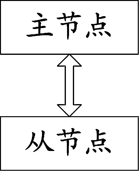
[0022] Such as figure 1 As shown, the system mainly includes the following parts:

[0023] The master node is used to send the start light signal to multiple slave nodes in the form of broadcast after sending the slave node light control information through the CAN bus;

[0024] The slave node receives the control information and the start light signal sent by the master node, executes the operation on the control information, and modifies the information of the slave node.

[0025] The master node includes a receiving module, which is used to receive the light control information of the slave node sent by the server.

[0026] After the slave node receives the control information and the start light signal sent by the master node, it further includes: unpacking and translating the received control information, and generating a light switch control signal and a...


PUM


Abstract

The invention discloses an intelligent lighting system based on a CAN bus. The system comprises a master node which is used for sending starting lamp signals to multiple slave nodes in a broadcasting mode after slave node lamp control information is sent; and the slave nodes which are used for receiving the control information and the starting lamp signals sent by the master node, executing control information operation and modifying slave node information. According to the intelligent lighting system based on the CAN bus, exchange of information between the master and slave nodes can be realized.

Description

technical field [0001] The invention relates to a lighting system, in particular to an intelligent lighting system based on CAN bus. [0002] Background technique [0003] Fieldbus is a fully decentralized, fully digital, intelligent, two-way, interconnected, multi-variable, multi-point, and multi-station communication network used between field instruments and control systems and control rooms. It is the basis of industrial data communication networks , which communicates the connection between field-level control equipment and its higher control management level in the production process. Since the field bus adapts to the development trend of industrial control systems towards decentralization, networking and intelligence, it has become a hot spot in global automation technology once it was produced. Its appearance has led to profound changes in the structure and equipment of the current production automation system. [0004] Illumination is the use of various light sou...

Claims


Application Information

Patent Timeline
Patent Type & Authority Applications(China)
IPC IPC(8): H05B37/02
CPCY02B20/42Y02B20/48Y02B20/40
Inventor 罗功坤秦宗伟
Owner GUANGXI UNIVERSITY OF TECHNOLOGY
Why Eureka
Try Eureka