Assembly room intelligent lighting linkage method and system

A technology of intelligent lighting and linkage system, which is applied in the field of meeting room lighting system, can solve the problem of inconvenient manual operation, and achieve the effect of eliminating the trouble of manual operation

Inactive Publication Date: 2015-07-15
SHANGHAI MICROSMART TECH
View PDF4 Cites 2 Cited by
  • Summary
  • Abstract
  • Description
  • Claims
  • Application Information

AI Technical Summary

Problems solved by technology

[0004] Manual operation is inconvenient, you need to get up to operate the lighting circuit switch, and there are usually several lighting circuits in the conference room, people who are not familiar with it still don't know how to operate, which switch corresponds to which group of lighting lights

Method used


Image

  • Assembly room intelligent lighting linkage method and system
  • Assembly room intelligent lighting linkage method and system
  • Assembly room intelligent lighting linkage method and system

Examples


Embodiment 1

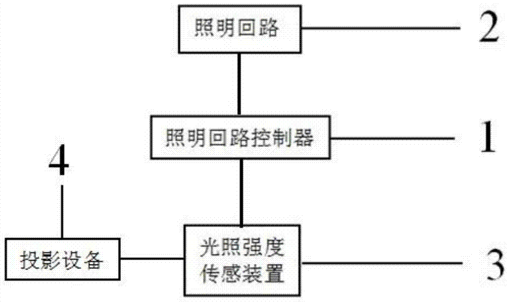
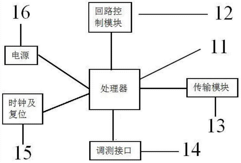
[0039] Such as figure 2 , image 3 , Figure 4 and Figure 5 As shown, the conference room intelligent lighting linkage system includes projection equipment 4, the conference room intelligent lighting linkage system includes a light intensity sensing device 3, a lighting loop controller 1 and a lighting loop 2, the light intensity sensing device 3 and The lighting circuit 2 is connected to the lighting circuit controller 1 respectively, and the illumination intensity sensing device 3 includes a projection position illumination intensity sensing device 301 and a non-projection position illumination intensity sensing device 302, and the projection position illumination intensity sensing device The device 301 and the non-projection position light intensity sensing device 302 are respectively connected to the lighting loop controller 1; the lighting loop controller 1 includes a processor 11, a loop control module 12, a transmission module 13, a clock and a reset 15, and Test i...

Embodiment 2

[0042] Such as Figure 6 As shown, the conference room intelligent lighting linkage system includes projection equipment 4, and the conference room intelligent lighting linkage system includes a light intensity sensing device 10 and a lighting circuit 20, and the light intensity sensing device 10 is connected to the lighting circuit 20 and the projection The device 4 is connected, and the illumination intensity sensing device 10 includes a projection position illumination intensity sensor 101, a non-projection position illumination intensity sensor 102 and a processor 103, and the projection position illumination intensity sensor 101 and the non-projection position illumination intensity sensor 102 are respectively connected with The processor 103 is connected; the processor 103 is connected with the lighting circuit 20 .

[0043] The light intensity sensor 101 at the projection position and the light intensity sensor 102 at the non-projection position send the detected light ...


PUM


Abstract

The present invention discloses an assembly room intelligent lighting linkage method and system. The assembly room intelligent lighting linkage method comprises the following steps: detecting projection position illumination intensity; detecting non-projection position illumination intensity; according to the projection position illumination intensity and the non-projection position illumination intensity, judging whether an illumination loop needs to be closed. According to the assembly room intelligent lighting linkage method and system provided by the present invention, the projection position illumination intensity and the non-projection position illumination intensity are detected; and according to both illumination intensity, it is judged whether to turn on or off a projector, and then on or off of the illumination loop is controlled; if the projector is turned on, the illumination loop is controlled to be closed, such that the projection watching is convenient and facilitated; and if the projector is turned off, the illumination loop is controlled to be opened, such that staffs in an assembly room can conveniently perform other events. Therefore, the intelligent illumination of the assembly room using the projector is achieved, and the inconvenience in manual operations is avoided.

Description

technical field [0001] The invention relates to a conference room lighting system, in particular to a conference room intelligent lighting linkage method and system. Background technique [0002] Often, conference room lighting needs to adjust in response to whether or not the projector is on. When there is no need to use the projector, whether the conference room lighting is on or off is determined by external factors such as natural light intensity; when the projector is needed, it is necessary to turn off part or all of the lighting to facilitate better projection viewing. [0003] The lighting and projector linkage methods currently used are all manual linkage. When the projector is turned on, turn off a lighting circuit or all lighting circuits manually; when the projector is turned off after use, manually turn on the lighting circuit switch. [0004] Manual operation is inconvenient, you need to get up to operate the lighting circuit switch, and there are usually sev...

Claims


Application Information

Patent Timeline
Patent Type & Authority Applications(China)
IPC IPC(8): H05B37/02
CPCY02B20/40
Inventor 郑洪渠郑春雷贾根团陈明李鹏宇金军
Owner SHANGHAI MICROSMART TECH
Why Eureka
Try Eureka