
Polygon mirror cavity structure and manufacturing method thereof

A manufacturing method and polygonal technology, applied in the direction of electrical components, circuits, semiconductor devices, etc., can solve problems such as stress generation, affecting mirror flatness and optical uniformity, mirror breakage, etc.

Inactive Publication Date: 2016-04-13
致茂电子(苏州)有限公司
View PDF3 Cites 0 Cited by
  • Summary
  • Abstract
  • Description
  • Claims
  • Application Information

AI Technical Summary

Problems solved by technology

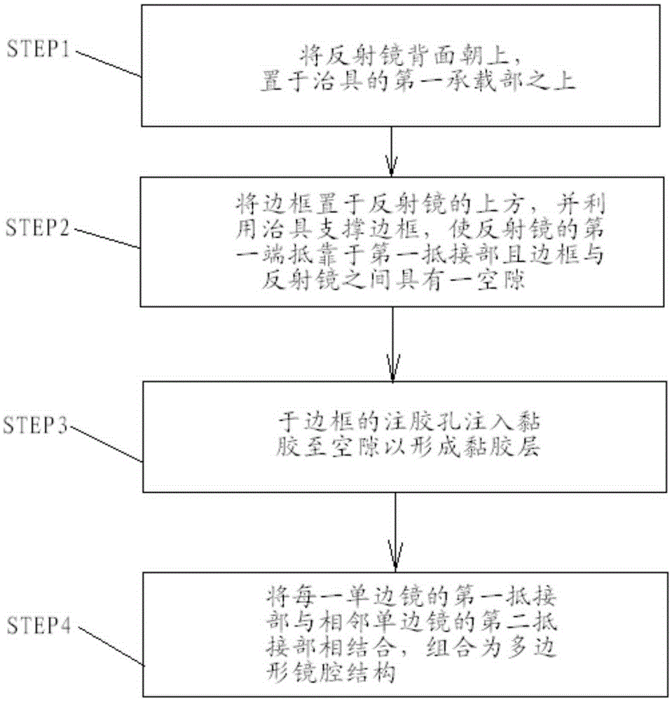
[0006] A common method for making a single-sided mirror unit contained in a polygonal mirror cavity is to lay the frame flat, apply glue on the inner surface of the frame facing up, and then place the reflector, or place the reflector flat, and place the reflector facing upward. Put glue on the back of the glass and place the frame, then apply pressure to facilitate the bonding of the mirror and the frame, and level the mirror and frame. However, the disadvantage of this method is that the glue solidifies and bonds under pressure. The mirror and frame are easy to generate stress inside, causing the mirror to deform and affect the flatness and optical uniformity of the mirror. In addition, when the mirror and frame are pressed, there is a risk of cracking the mirror

Method used


Image

  • Polygon mirror cavity structure and manufacturing method thereof
  • Polygon mirror cavity structure and manufacturing method thereof
  • Polygon mirror cavity structure and manufacturing method thereof

Examples


Embodiment Construction

[0083] In order to enable your review committee members to have a further understanding and understanding of the characteristics of the present invention and the achieved effects, I would like to provide preferred embodiments and detailed descriptions, as follows:

[0084] The invention proposes a polygonal mirror cavity structure and its manufacturing method, which is characterized in that: each single-sided mirror can adjust the thickness of the adhesive layer to offset the influence of the thickness tolerance caused by the production of the mirror, and maintain the single-sided mirror. The overall thickness keeps an appropriate gap between two adjacent mirrors to avoid light leakage or collision damage. In addition, one end of each single-sided mirror can form an accommodating space to accommodate the other end of the adjacent single-sided mirror. The space can buffer the length tolerance caused by the manufacture of the reflector, so that the length tolerance will not affec...


PUM


Abstract

The invention discloses a polygonal mirror cavity structure and a manufacturing method thereof. The polygonal mirror cavity structure is formed by assembling a plurality of unilateral mirrors; each unilateral mirror comprises a frame, a reflector and an adhesive layer, one end of each frame is convexly provided with a first abutting part, the other end of the frame is provided with a second abutting part, the corresponding reflector is arranged on the inner surface of the frame, and the adhesive layer is arranged between the frame and reflector; when the unilateral mirrors are assembled to form the polygonal mirror cavity structure, each reflector faces the inner side, the top surface of the first abutting part of each unilateral mirror is jointed with the second abutting part of an adjacent unilateral mirror; during manufacture, frames and reflectors are respectively supported by jigs to keep gaps therebetween, an adhesive is injected, flows to fill the gaps and is naturally coagulated, and stress generated internally can be prevented to avoid the deformation of the reflectors, so that the flatness and the optical homogeneity of the mirror surface are not influenced.

Description

technical field [0001] The present invention relates to a polygonal mirror cavity structure and its manufacturing method, more specifically, a single-sided mirror composed of multiple single-sided mirrors whose structure and manufacturing process can reduce the bonding stress of the mirror and the frame, At the same time, the polygonal mirror cavity structure can reduce the influence of component tolerances on assembly. Background technique [0002] The principle of light emitting diode (light emitting diode, LED) is to use an external voltage to combine electrons and holes in the semiconductor, and release energy in the form of light energy. Early LEDs only have two types of red light and green light, and cannot produce white light yet. At that time, LEDs were mainly used in the production of indicator lights. It was not until 1994 that Nichia Corporation of Japan developed blue LEDs, which made it possible to produce white light with LEDs. With the advantages of low voltag...

Claims


Application Information

Patent Timeline
Patent Type & Authority Patents(China)
IPC IPC(8): H01L33/60
CPCH01L33/60H01L2933/0058
Inventor 李泓锡张添登翁义龙
Owner 致茂电子(苏州)有限公司
Learn More