
Illuminated Water Bottle Cage

一种水壶架、水壶的技术,应用在光源、发光元件的半导体器件、点状光源等方向,能够解决占空间、安装不方便、成本高等问题,达到扩大光散射面积、使用简单与方便、控制生产成本的效果

Inactive Publication Date: 2014-09-24
TOPEAK INC
View PDF5 Cites 0 Cited by
  • Summary
  • Abstract
  • Description
  • Claims
  • Application Information

AI Technical Summary

Problems solved by technology

[0003] However, because consumers usually choose to buy low-priced water bottle cages, the price of the water bottle cage cannot be too high, so the light-emitting unit can only use low-cost lamps as the light source, but this will lead to substantial nighttime lighting. The warning lighting ability is not good, because the lamps with multiple light-emitting units do not design additional reflectors for the light-emitting units, so when the light-emitting units are viewed at night, the naked eye can only find a weak single-point light source, which cannot achieve true night warning effect
[0004] If a reflector is used to focus and improve the light-gathering ability of the light-emitting element, the cost will be too high, and the entire lamp will be relatively large. If the lamp is installed on the bottle cage, the appearance of the bottle cage will be abrupt and difficult. It is inconvenient to install and takes up space, and cannot even meet the requirements of lightness, so it is difficult to be accepted by consumers
[0005] Furthermore, the light-emitting unit is located in front of the pot holder, and the front edge of the pot-bearing space is provided with the above-mentioned light-emitting unit, which is easy to collide with other objects in the outside world and be damaged.
[0006] In addition, the light-emitting unit located in front of the pot seat is also prone to dust accumulation, or damage caused by rain, because the rider rides through muddy areas or rides in rainy days, the light-emitting unit will be reduced service life

Method used


Image

  • Illuminated Water Bottle Cage
  • Illuminated Water Bottle Cage
  • Illuminated Water Bottle Cage

Examples


Embodiment Construction

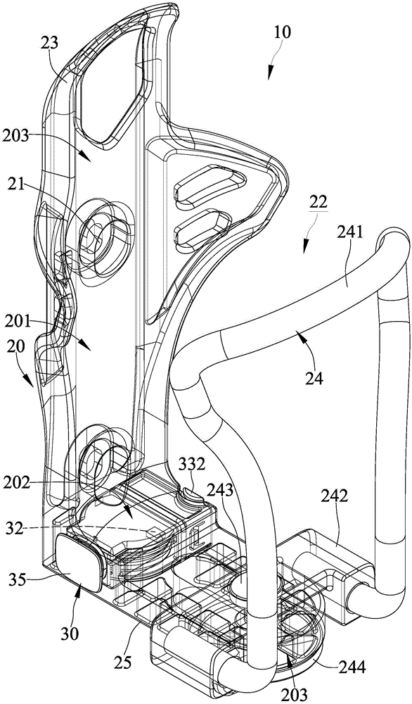
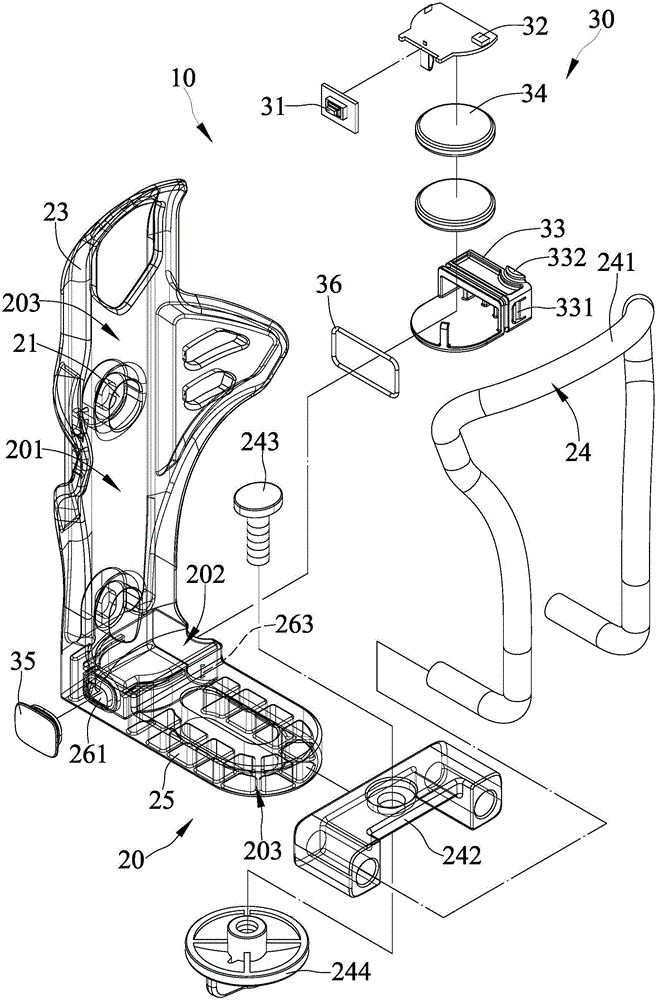
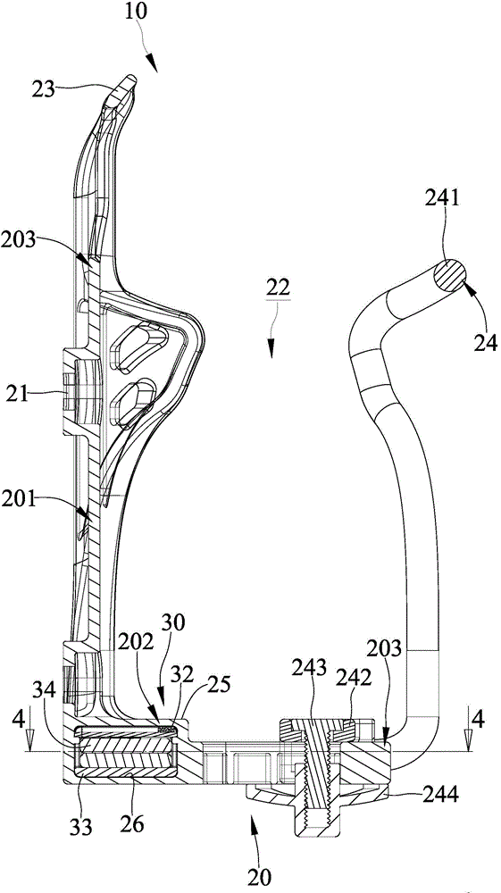
[0024] refer to figure 1 and figure 2 , is the first embodiment of the luminous water bottle cage 10 of the present invention. The luminous water bottle stand 10 of this embodiment includes a placement base 20 and a light emitting device 30. The placement base 20 is provided with a light-transmitting area 201 for the light source projection of the light-emitting device 30 to diffuse the light-transmitting area 201 of the water bottle rack 10. The light source achieves the effect of increasing the light scattering area to improve the night warning function; among them:

[0025] Please also refer to image 3 One side of the placement seat 20 is provided with a joint part 21, and the joint part 21 can be combined with the bicycle. The placement base 20 defines an accommodating space 22 extending along the axial direction of the placement base 20, and the accommodating space 22 can accommodate a kettle.

[0026] The base 20 is provided with a light-transmitting area 201 . The...


PUM


Abstract

An illuminated water bottle cage comprises a holder base having a light transmission section and a light-emitting device. One side of the holder base is provided with a coupling portion able to be mounted to a bicycle. The holder base is provided with a receiving space extending along a longitudinal axis of the holder base to receive a water bottle. The light transmission section comprises an incident portion and a light guiding portion. The light-emitting device is mounted in the light transmission section of the holder base. A light source of the light-emitting device is projected onto the incident portion of the light transmission section, allowing light beams projected onto the incident portion to be transmitted to the light guiding portion, and diffusing the light source of the light-emitting device to the light transmission section of the holder base to achieve the effect of diffusing the light source of the lighting device, the light scattering area of the holder base can effectively be increased to enhance the function of nighttime warning.

Description

technical field [0001] The invention mainly discloses a luminous water bottle stand, especially a light-emitting bottle stand with a light-transmitting area for a light source projected by a light-emitting device to diffuse the light source in the light-transmitting area of ​​the water bottle stand to increase the light scattering area. Background technique [0002] Referring to the CN201484558 patent case of the People's Republic of China, it discloses a water bottle stand with a light-emitting function, which can be hung on a car body and accommodate a water bottle. The water bottle stand includes a pot seat and At least one light-emitting unit, wherein the pot holder includes a fixed part that can be mounted on the car body, and a kettle bearing part that defines a kettle-bearing space for the placement of a kettle, and the kettle bearing that the light-emitting unit is installed on the kettle holder On the part, by virtue of the luminous unit arranged on the pot holder, ...

Claims


Application Information

Patent Timeline
Patent Type & Authority Applications(China)
IPC IPC(8): B62J11/00B62J6/00
CPCF21Y2101/02B62J11/00F21V33/008F21Y2115/10B62J11/04B62J6/16
Inventor 庄士文
Owner TOPEAK INC
Learn More