
Novel unmanned aerial vehicle charging supply device for power transmission line

A technology for transmission lines and unmanned aerial vehicles, which is applied in the field of new-type unmanned aerial vehicle charging and supply devices for transmission lines, can solve the problems of large power consumption and cumbersome charging methods, and achieve the effect of avoiding damage.

Inactive Publication Date: 2020-08-18
LUOYANG INST OF ELECTRO OPTICAL EQUIP OF AVIC
View PDF4 Cites 0 Cited by
  • Summary
  • Abstract
  • Description
  • Claims
  • Application Information

AI Technical Summary

Problems solved by technology

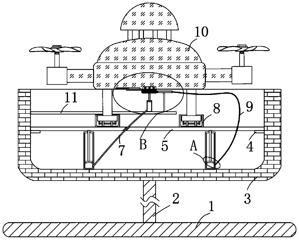
[0003] The drone needs to consume a lot of power during flight. The traditional way is that the drone lands on the charging pile, and the dust cover at the socket needs to be manually opened, and then the plug is inserted into the socket for charging. After the charging is completed, Manually pull out the plug, close the dust cover, and realize the charging of the drone. This charging method is cumbersome and requires manual assistance. Therefore, an automatic charging method is urgently needed to realize the charging of the drone. Therefore, we propose a new type of UAV charging and replenishing device for transmission lines to solve the above problems

Method used


Image

  • Novel unmanned aerial vehicle charging supply device for power transmission line
  • Novel unmanned aerial vehicle charging supply device for power transmission line
  • Novel unmanned aerial vehicle charging supply device for power transmission line

Examples


Embodiment Construction

[0024] The following will clearly and completely describe the technical solutions in the embodiments of the present invention with reference to the accompanying drawings in the embodiments of the present invention. Obviously, the described embodiments are only some, not all, embodiments of the present invention.

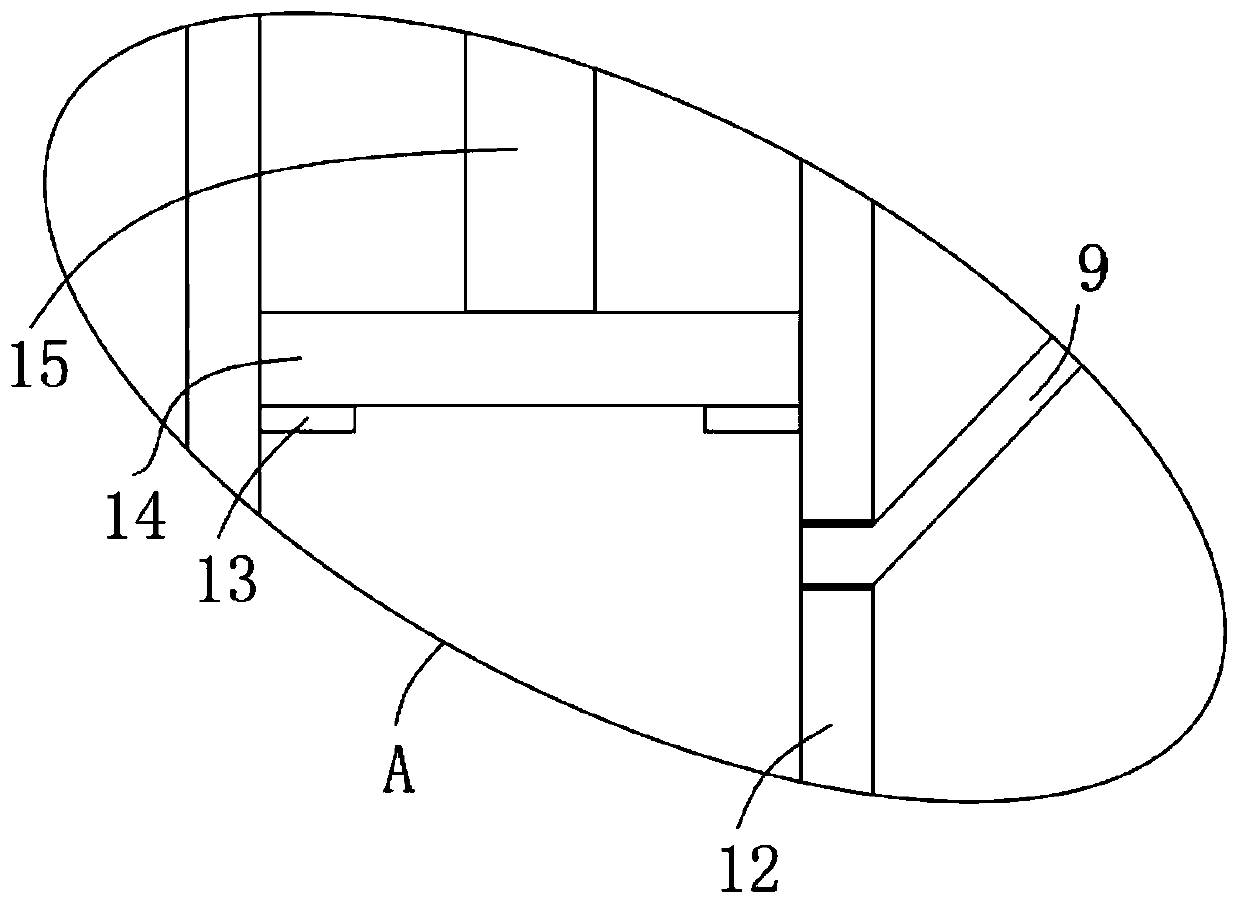
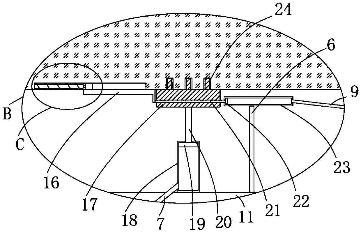
[0025] refer to Figure 1-5 , a new type of UAV charging supply device for transmission lines, including a base 1, the upper end of the base 1 is fixedly connected to a support column 2, the upper end of the support column 2 is fixedly connected to an installation box 3, and a sliding plate 5 is slidably connected to the installation box 3 , the inner side wall of the installation box 3 is fixedly installed with two limit blocks 4, the upper ends of the two limit blocks 4 are pressed against the lower side wall of the sliding plate 5, and the inner bottom of the installation box 3 is symmetrically provided with two buffer mechanisms, The buffer mechanism not only rea...


PUM


Abstract

The invention discloses a novel unmanned aerial vehicle charging supply device for a power transmission line. The device relates to the technical field of unmanned aerial vehicle replenishment, and includes a base, the upper end of the base is fixedly connected with a supporting column. The upper end of the supporting column is fixedly connected with a mounting box; a sliding plate is connected into the mounting box in a sliding manner; two limiting blocks are fixedly mounted on the inner side wall of the mounting box; the upper ends of the two limiting blocks abut against the side wall of thelower end of the sliding plate. Two buffer mechanisms are symmetrically arranged at the inner bottom of the mounting box; the upper ends of the two buffer mechanisms are fixedly connected with the side wall of the lower end of a sliding plate; the inner side wall of the base is fixedly connected with a fixed plate; and a pushing mechanism is fixedly connected to the side wall of the upper end ofthe fixing plate, through cooperative use of a telescopic rod, a first spring, a moving block and a sealing plate, sealing of the inserting hole is achieved, dust is effectively prevented from entering the inserting hole in the flying process of the unmanned aerial vehicle, and therefore the situation that charging is affected is avoided.

Description

technical field [0001] The invention relates to the technical field of unmanned aerial vehicles, in particular to a new charging and supplying device for unmanned aerial vehicles on power transmission lines. Background technique [0002] Unmanned aircraft, referred to as "UAV", is an unmanned aircraft controlled by radio remote control equipment and its own program control device. Unmanned aerial vehicle is actually a general term for unmanned aircraft. It has the advantages of small size and low cost. , Easy to use, UAVs can be divided into military and civilian use according to the application field. In terms of military use, UAVs are divided into reconnaissance aircraft and target aircraft. In terms of civilian use, drones + industry applications are the real rigid needs of drones; currently, they are used in aerial photography, agriculture, plant protection, micro selfies, express delivery, disaster relief, wildlife observation, infectious disease monitoring, surveying a...

Claims


Application Information

Patent Timeline
IPC IPC(8): B60L53/16B60L53/30B64F1/00
CPCB64F1/00B60L53/16B60L53/30Y02T10/70Y02T10/7072Y02T90/12Y02T90/14Y02T90/16
Inventor 陈国强丁建王彬孙志勇赵春梅
Owner LUOYANG INST OF ELECTRO OPTICAL EQUIP OF AVIC
Learn More