
Detection device for unmanned aerial vehicle-mounted electronic system

A technology for testing equipment and electronic systems, applied in electrical testing/monitoring, etc., can solve the problem of shortening the service life of flight control stations and ground data terminals, increasing the maintenance workload of UAV fleet equipment, prolonging UAV system detection time, etc. problem, to achieve the effect of improving informatization capability, avoiding spurious frequency or ring loss of lock, and fast detection speed

Active Publication Date: 2014-04-23
NO 63908 TROOPS PLA
View PDF6 Cites 26 Cited by
  • Summary
  • Abstract
  • Description
  • Claims
  • Application Information

AI Technical Summary

Problems solved by technology

The above detection methods have brought great inconvenience to the combat training of the troops, mainly as follows: (1) Limiting the number of UAV system detection sorties; (2) The detection data is not comprehensive enough; (3) Extending the UAV system (4) Shorten the service life of the flight control station and ground data terminal; (5) Increase the electromagnetic damage to the inspectors
It can be seen that the detection of the traditional avionics system has greatly increased the daily equipment maintenance workload of the UAV team and caused a certain degree of fear in the troops. In order to reduce the dispatch rate of equipment vehicles and personnel dispatch rate, some troops generally Deliberately avoiding the maintenance of drone avionics equipment, which seriously affects the life of the equipment

Method used


Image

  • Detection device for unmanned aerial vehicle-mounted electronic system
  • Detection device for unmanned aerial vehicle-mounted electronic system
  • Detection device for unmanned aerial vehicle-mounted electronic system

Examples


Embodiment Construction

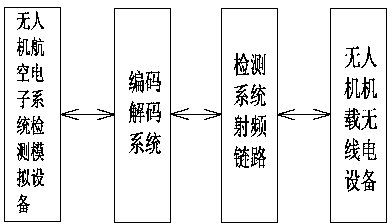
[0025] like figure 1 As shown, a UAV airborne electronic system detection equipment includes a UAV avionics system detection simulation equipment, a codec system and a radio frequency link of the detection system. The detection and simulation equipment of the UAV avionics system is connected to the encoding and decoding system through the serial port, and the encoding and decoding system is connected to the onboard radio equipment of the UAV through the radio frequency link of the detection system.

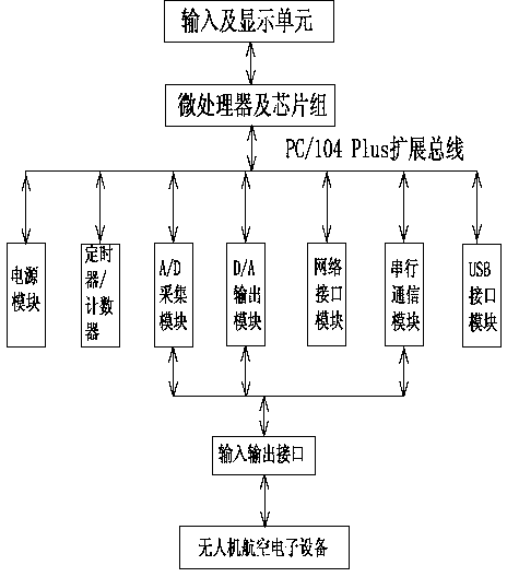
[0026] like figure 2 As shown, the detection and simulation equipment of the UAV avionics system includes an input and display unit, a microprocessor and a chipset, a power supply module, a timer counter, an A / D acquisition module, a D / A output module, and a serial communication module , Network interface module and USB interface module. The measured signal is input to the A / D acquisition module and serial communication module through the input and output interface, and then tr...


PUM


Abstract

The invention, which belongs to the technical field of the unmanned aerial vehicle detection apparatus, discloses a detection device for an unmanned aerial vehicle-mounted electronic system. The detection device comprises an unmanned aerial vehicle avionics system detection simulation device, a coding and decoding system, and a detection system radio frequency link; the unmanned aerial vehicle avionics system detection simulation device is connected with the coding and decoding system by a serial port; and the coding and decoding system is connected with unmanned aerial vehicle-mounted radio equipment by the detection system radio frequency link. According to the detection device, the miniaturized and portable design scheme is used; the detection workload is small; a few responders are needed; and the detection speed is fast. On the basis of the mode of wired connection of the detection system radio frequency link with the unmanned aerial vehicle-mounted radio equipment, problems that frequent starting up by the ground control station is needed and the collision with self examination of the ground control station exists during the detection process of the unmanned aerial vehicle-mounted electronic system can be solved.

Description

technical field [0001] The invention relates to the technical field of unmanned detection devices, in particular to a detection device for an on-board electronic system of an unmanned aerial vehicle. Background technique [0002] The UAV airborne electronic system includes the avionics system and the airborne radio system. Positioning and navigation, mission equipment control and management, remote control signal reception, decoding and data processing, telemetry signal coding and transmission and many other important tasks. Therefore, the performance and reliability of the system have an important impact on the combat capability of the medium-range UAV system. Once a failure occurs, it may cause devastating damage to the UAV. [0003] There are two ways to detect the onboard electronic system of the UAV: ​​1. The technical position detection before flight. When this detection method is used for detection, more vehicles and personnel need to be dispatched, and the detection...

Claims


Application Information

Patent Timeline
Patent Type & Authority Applications(China)
IPC IPC(8): G05B23/02
Inventor 吕艳梅王格芳张东韩宁孙江生连光耀陈卫王春龙柴景运
Owner NO 63908 TROOPS PLA
Learn More