A Method for Detecting Transformer Winding Deformation

A technology for transformer windings and transformers, which is applied in the measurement of electrical variables, instruments, and electrical measurement, can solve problems such as poor anti-interference, unclear criteria, and undiagnosed results, and achieve high accuracy and improve accuracy. Effect

Active Publication Date: 2016-04-27
XI AN JIAOTONG UNIV
View PDF7 Cites 0 Cited by
  • Summary
  • Abstract
  • Description
  • Claims
  • Application Information

AI Technical Summary

Problems solved by technology

[0004] In general, among the current transformer winding deformation measurement methods, the short-circuit reactance method has clear criteria, but the anti-interference performance is poor and the type and location of the fault cannot be diagnosed; while the frequency response method is sensitive in measurement and has better anti-interference performance, but the criterion is not Clear, diagnosis requires more practical experience
In order to discover potential transformer failures in time, avoid unexpected accidents, and improve the safety and reliability of transformer operation, it is of great significance to carry out research on the detection of transformer winding deformation using the frequency response method combined with the short-circuit reactance method. However, this simple combination still adopts its own Instruments and equipment, the test process is cumbersome, and the diagnostic results of the two methods are not well combined

Method used


Image

  • A Method for Detecting Transformer Winding Deformation
  • A Method for Detecting Transformer Winding Deformation
  • A Method for Detecting Transformer Winding Deformation

Examples


Embodiment Construction

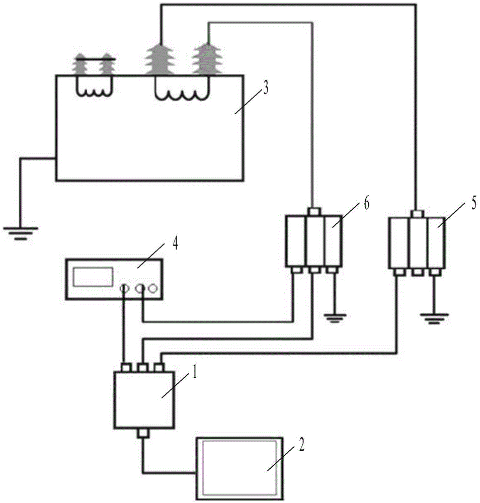
[0022] The present invention is described in further detail below in conjunction with accompanying drawing:

[0023] refer to figure 1 , the system for detecting transformer winding deformation of the present invention includes a controller 2, an HS3 multifunctional signal generator 1, a power amplifier 4, a first sampling resistor 5, a second sampling resistor 6 and a test transformer 3; the HS3 multifunctional The input terminal of the functional signal generator 1 is respectively connected with the output terminal of the controller 2, the output terminal of the power amplifier 4 and the end of the winding in the test transformer 3, and the output terminal of the HS3 multifunctional signal generator 1 is connected with the terminal of the controller 2 respectively. Input end, the input end of power amplifier 4 are connected, and the output end of power amplifier 4 is connected with the start end of winding in test transformer 3; The first sampling resistor 5 is connected, a...


PUM


Abstract

The invention provides a system for detecting transformer winding deformation. The system comprises a controller 2, an HS3 multifunctional signal generator, a power amplifier, a first sampling resistor, a second sampling resistor and a testing transformer. An input end of the HS3 multifunctional signal generator is respectively connected with an output end of the controller, an output end of the power amplifier and a tail end of a winding in the testing transformer. An output end of the HS3 multifunctional signal generator is respectively connected with an input end of the controller and an input end of the power amplifier. The output end of the power amplifier is connected with a start end of the winding in the testing transformer. The input end of the HS3 multifunctional signal generator is connected with the tail end of the winding in the testing transformer through the first sampling resistor. The output end of the power amplifier and the start end of the winding in the testing transformer are connected through the second sampling resistor. The invention also provides a method for detecting transformer winding deformation. By the adoption of the system and the method, accuracy for detecting transformer winding deformation can be raised effectively.

Description

technical field [0001] The invention relates to a system and method for detecting transformers, in particular to a system and method for detecting deformation of transformer windings. Background technique [0002] With the rapid development of the national economy, the power system is growing continuously, and the demand for various power equipment is also increasing. As an important equipment in the system, the traditional power transformer has a high failure rate. If a large-scale power transformer fails during operation, it will cause a large-scale and long-term power outage in an area, causing major economic losses and giving inconvenience to people's lives. Relevant statistical data in recent years show that transformer windings are the most faulty parts. The accidents of 110kV and above power transformers in the country due to external short-circuit faults have reached 50% of the total number of accidents. From the perspective of disintegration inspections, most of th...

Claims


Application Information

Patent Timeline
Patent Type & Authority Patents(China)
IPC IPC(8): G01R31/06
Inventor 汲胜昌梁笑尘刘勇
Owner XI AN JIAOTONG UNIV
Why Eureka
Try Eureka