Ultrasonic flowmeter

An ultrasonic and flowmeter technology, used in the measurement of flow/mass flow, liquid/fluid solid measurement, measurement devices, etc., can solve problems such as inability to measure flow with high accuracy, measurement flow, error, etc., and achieve the effect of high-precision flow measurement

Inactive Publication Date: 2014-04-16
HORIBA LTD
View PDF1 Cites 0 Cited by
  • Summary
  • Abstract
  • Description
  • Claims
  • Application Information

AI Technical Summary

Problems solved by technology

In this way, errors occur in the measurement of the propagation time of ultrasonic vibration and the difference in propagation time, and there is a problem that the flow rate cannot be measured with high accuracy.

Method used


Image

  • Ultrasonic flowmeter
  • Ultrasonic flowmeter
  • Ultrasonic flowmeter

Examples


Embodiment Construction

[0044] The ultrasonic flowmeter of the present invention will be described below with reference to the drawings.

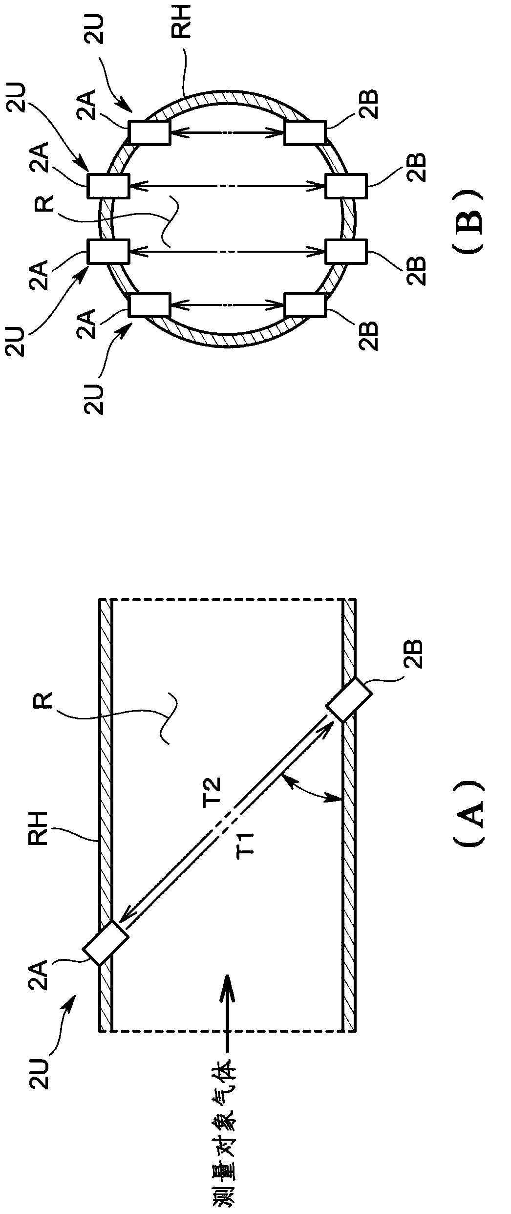
[0045] The ultrasonic flowmeter 100 of the present embodiment is used in a gas analysis system that analyzes components contained in a gas to be measured, such as exhaust gas discharged from an engine, etc. The gas flow pipe RH of the gas is used to measure the flow rate of the measurement target gas flowing through the flow channel R of the gas flow pipe RH.

[0046] Specific as figure 1 As shown in (A), the ultrasonic flowmeter 100 has a plurality of pairs of first ultrasonic transmitter receivers 2A and second ultrasonic transmitter receivers arranged obliquely in the flow channel R of the gas flow pipe RH 2B. In the present embodiment, the first ultrasonic transceiver 2A is installed on the upstream side, and the second ultrasonic transceiver 2B is installed on the downstream side. In addition, if figure 1 As shown in (B), in the plurality of ultrasonic ...


PUM


Abstract

The present invention provides an ultrasonic flowmeter that suppresses crosstalk caused by switching means adapted to switch transmission / reception between ultrasonic transceivers that are paired. The ultrasonic flowmeter is provided with: a first ultrasonic transceiver 2A and a second ultrasonic transceiver 2B; a transmission circuit 3 that generates a transmission signal for vibrating the first ultrasonic transceiver 2A or the second ultrasonic transceiver 2B; a reception circuit 4 that senses a reception signal from the first ultrasonic transceiver 2A or the second ultrasonic transceiver 2B; first transmission amplifying means 7A adapted to amplify the transmission signal to the first ultrasonic transceiver 2A; first reception amplifying means 8A adapted to amplify a reception signal from the first ultrasonic transceiver 2A; second transmission amplifying means 7B adapted to amplify the transmission signal to the second ultrasonic transceiver 2B; and second reception amplifying means 8B adapted to amplify a reception signal from the second ultrasonic transceiver 2B.

Description

technical field [0001] The present invention relates to ultrasonic flow meters. Background technique [0002] As shown in Patent Document 1, an ultrasonic flowmeter in the past includes: a pair of first ultrasonic transmitter receivers and second ultrasonic transmitter receivers; a transmitter circuit that outputs transmission signals to these ultrasonic transmitter receivers; a receiver circuit that detects The receiving signal of the ultrasonic transmitter receiver; and the switching device, switching the transmission and reception of the first ultrasonic transmitter receiver and the second ultrasonic transmitter receiver. [0003] and if Figure 6 As shown, the switching device includes: a switch SW1, which is used to switch whether to output the transmission signal from the transmission circuit to the first ultrasonic transmitter receiver; a switch SW3, which is used to switch whether to transmit and receive the transmission signal to the second ultrasonic wave. The swi...

Claims


Application Information

Patent Timeline
Patent Type & Authority Applications(China)
IPC IPC(8): G01F1/66
CPCG01F1/667
Inventor 栗秋和典
Owner HORIBA LTD
Why Eureka
Try Eureka