Diffusion plate, backlight module and display device

A technology of backlight module and diffuser plate, which is applied to lighting devices, fixed lighting devices, components of lighting devices, etc. Improve the effect of divergence, good divergence and uniform brightness

Inactive Publication Date: 2014-04-16
BOE TECH GRP CO LTD +1
View PDF6 Cites 7 Cited by
  • Summary
  • Abstract
  • Description
  • Claims
  • Application Information

AI Technical Summary

Problems solved by technology

[0003] figure 1 It is a schematic diagram of the structure of the existing backlight module. The diffusion plate 1 in the existing backlight module is a flat structure. On the diffuser plate 1, since the existing backlight modules usually use light-emitting elements such as LEDs as light sources, and light-emitting elements such as LEDs have a certain light-emitting angle, there needs to be a sufficient light mixing distance, that is, to maintain a certain distance between the light source and the diffuser plate. In order to make the light emitted by the light source evenly irradiate the diffuser plate, it is conducive to the divergence of light and avoid bright spots on the backlight module due to insufficient light mixing distance, but when the number of light sources is larger or the spacing is smaller , the existing backlight module using a flat diffuser plate needs to increase the light mixing distance to make the light uniformly diverge, which will increase the thickness of the backlight module, making it difficult to thin the entire backlight module

Method used


Image

  • Diffusion plate, backlight module and display device
  • Diffusion plate, backlight module and display device
  • Diffusion plate, backlight module and display device

Examples


Embodiment Construction

[0024] The diffusion plate, the backlight module and the display device according to the embodiments of the present invention will be described in detail below with reference to the accompanying drawings.

[0025] In describing the present invention, it is to be understood that the terms "center", "upper", "lower", "front", "rear", "left", "right", "vertical", "horizontal", The orientations or positional relationships indicated by "top", "bottom", "inner", "outer", etc. are based on the orientations or positional relationships shown in the drawings, and are only for the convenience of describing the present invention and simplifying the description, rather than indicating or implying References to devices or elements must have a particular orientation, be constructed, and operate in a particular orientation and therefore should not be construed as limiting the invention.

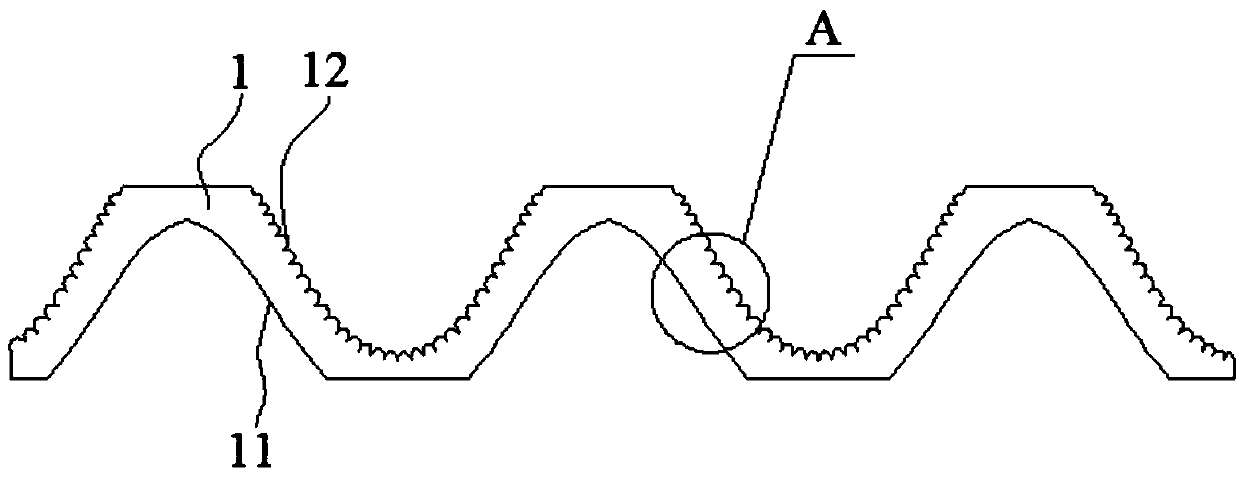
[0026] refer to figure 2 , figure 2 It is a specific embodiment of the diffusion plate of the embodim...


PUM


Abstract

The invention discloses a diffusion plate, a backlight module and a display device, and relates to the technical field of liquid crystal display. The diffusion plate comprises a light incident surface and a light emergent surface. Concave surfaces for receiving incident light rays are formed in the light incident surface, and convex surfaces which correspond to the concave surfaces and are used for emerging light rays are arranged on the light emergent surface. The diffusion plate, the backlight module and the display device have the advantages that the backlight module is thin, and the diffusion plate is used for the backlight module.

Description

technical field [0001] The invention relates to the technical field of liquid crystal display, in particular to a diffusion plate, a backlight module and a display device. Background technique [0002] Liquid crystal display, as a non-self-luminous display device, needs to be used together with a backlight module to display images normally. At present, the backlight module usually uses LED (Light Emitting Diode, light emitting diode), CCFL (Cold Cathode Fluorescent Lamp, cold cathode fluorescent tube) as light-emitting elements, in the direct-lit backlight module, in order to make the light emitted by the backlight more uniform and provide sufficient and uniform light source for the liquid crystal display, a diffuser plate is generally installed in the backlight module to diverge the light More uniform, so as to provide a uniform surface light source for the liquid crystal display. [0003] figure 1 It is a schematic diagram of the structure of the existing backlight modul...

Claims


Application Information

Patent Timeline
Patent Type & Authority Applications(China)
IPC IPC(8): F21V5/08F21S8/00G02F1/13357F21Y101/02
Inventor 李友布占场金雄
Owner BOE TECH GRP CO LTD
Why Eureka
Try Eureka