
A kind of pulling reel hose assembly

A technology of hose assembly and plucking wheel, which is applied in the direction of hose, pipe, pipe/pipe joint/pipe fitting, etc. To the effect of compact structure, improved service life and convenient operation

Active Publication Date: 2016-05-04
广州市艾美塑胶软管有限公司
View PDF6 Cites 0 Cited by
  • Summary
  • Abstract
  • Description
  • Claims
  • Application Information

AI Technical Summary

Problems solved by technology

[0006] One end of the existing puller hose is connected to the hydraulic system with a flange, which has poor sealing performance. The other end is connected to the oil inlet pipe in a socket type, and the surface is covered with a cylindrical sleeve. low and poor radial bearing capacity, the present invention provides a reel hose assembly, one end connected to the hydraulic system is connected with a ball joint to increase the sealing performance, and it is changed to a rolling sleeve to increase Radial load, increased service life

Method used


Image

  • A kind of pulling reel hose assembly
  • A kind of pulling reel hose assembly
  • A kind of pulling reel hose assembly

Examples


Embodiment 1

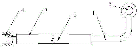
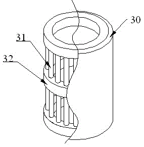
[0024] Such as figure 1 , figure 2 as well as image 3 As shown, a puller hose assembly includes a hose 1, a rubber hose 2, a sleeve 3, a nut 4 and a ball joint 5, and the nut 4 and the rubber hose 2 are connected to the rubber hose in a socket type. Both ends of 2 and the surface of the connection are provided with sleeves 3; the sleeve 3 includes a casing 30, a needle roller 31 and a connecting ring 32; the casing 30 is fixed on the outermost side of the sleeve 3; there are three connecting rings 32, which are respectively located The upper, middle and lower positions of cylinder 3. The needle rollers 31 all pass through the connecting ring 32 in the middle, and the two ends are respectively located in the upper and lower connecting rings 32. The sleeve with this structure has a compact radial structure, can withstand higher radial loads, and its rigidity It is higher than the general cylindrical sleeve, and the needle roller 31 can freely roll relative to the connectin...

Embodiment 2

[0028] Same as embodiment 1, the difference is that the number of needle rollers 31 is preferably 20, increasing the number of needle rollers 31 makes the radial load capacity of the sleeve 3 higher.


PUM


Abstract

The invention discloses a reel hose assembly, which belongs to the field of pipelines. It includes a hose, a rubber hose, a sleeve, and a nut and a ball joint. The nut and the rubber hose are connected to both ends of the rubber hose in a socket type, and the surface of the joint is provided with a sleeve; The sleeve includes a shell, a needle roller and a connecting ring; the shell is fixed on the outermost layer of the sleeve; there are three connecting rings, which are respectively located at the upper, middle and lower positions of the sleeve; the roller There are N needles, all of which pass through the middle connecting ring, and the two ends are respectively located in the upper and lower connecting rings, and can freely roll relative to the connecting ring; the ball joint is located at the other end of the hose. In the present invention, one end connected with the hydraulic system is connected with a ball joint to increase the sealing performance, and is changed to a rolling sleeve to increase the radial load and improve the service life.

Description

Technical field [0001] The present invention involves a pipeline assembly structure, especially a pipeline hose assembly. Background technique [0002] The pull -up wheel is mainly used for the crooked harvester or the combined harvester cutting table to guide the stem poles, support the cutting, and clean the table to prevent the stem rods from accumulating the cutting knife and cause the sword. [0003] In the hydraulic and hydraulic transmission technology, the manipulating valve is the operating valve or the control valve, with the direction valve, pressure valve, flow valve, etc.The manipulation is the purpose of driving the valve through hydraulic or hydraulic force to reach the purpose of the control direction (deduction), pressure or flow. These valves are manual and automatic.Connecting the manipulating valve with the oil inlet pipe of the hydraulic system can not only achieve the operation of the manipulation valve. Since the control valve is controlled by hydraulic or ...

Claims


Application Information

Patent Timeline
Patent Type & Authority Patents(China)
IPC IPC(8): F16L11/00A01D69/03
CPCA01D69/03
Inventor 罗琳
Owner 广州市艾美塑胶软管有限公司
Learn More