
Conical roller bearing automatic feed and face recognizing machine

A tapered roller bearing and automatic feeding technology, applied in the direction of conveyor objects, transportation and packaging, can solve the problems of wasting manpower, low production efficiency, unable to guarantee consistent upward or downward, etc., to save costs and reduce labor. the effect of strength

Inactive Publication Date: 2014-04-16
慈溪市伊纳轴承有限公司
View PDF8 Cites 24 Cited by
  • Summary
  • Abstract
  • Description
  • Claims
  • Application Information

AI Technical Summary

Problems solved by technology

Because the inner and outer rings of the tapered roller bearing are tapered raceways, the areas of the front and back of the tapered roller bearing are different. It can also be said that the diameters of the two ends of the inner hole of the tapered roller bearing are different. When grinding the raceway of tapered roller bearings, it is impossible to ensure that the faces of all products are consistent up or down, which is random
[0003] At present, before the grinding process of tapered roller bearings, it is necessary to manually turn over the arrangement of tapered roller bearings one by one. Generally, the end with the larger inner hole faces upwards and the end with the smaller inner hole faces downwards. However, due to the large size difference Small, the shape of the front and back is similar, the human eye cannot distinguish quickly and without errors, resulting in error-prone, waste of manpower, high production costs, low production efficiency, etc.

Method used


Image

  • Conical roller bearing automatic feed and face recognizing machine
  • Conical roller bearing automatic feed and face recognizing machine
  • Conical roller bearing automatic feed and face recognizing machine

Examples


specific Embodiment approach

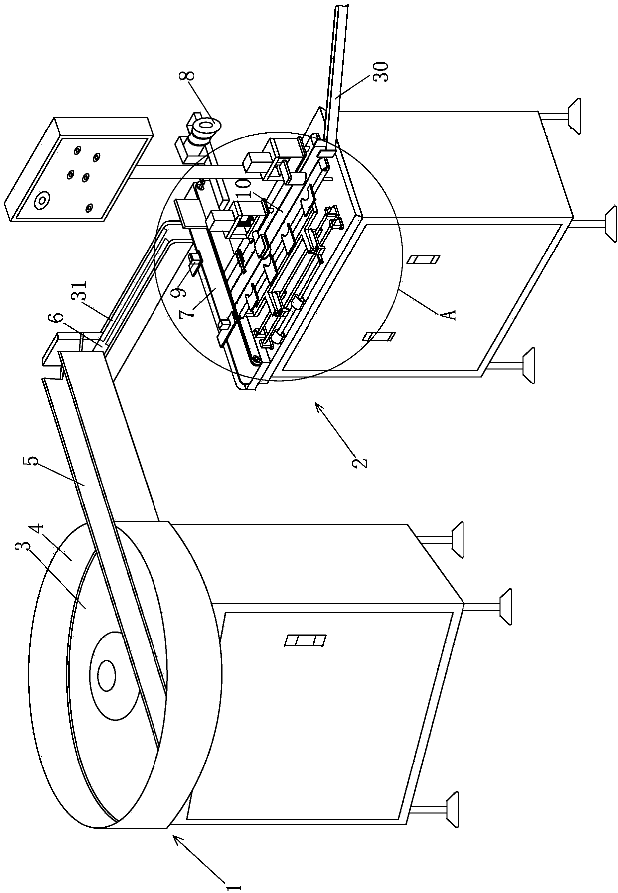
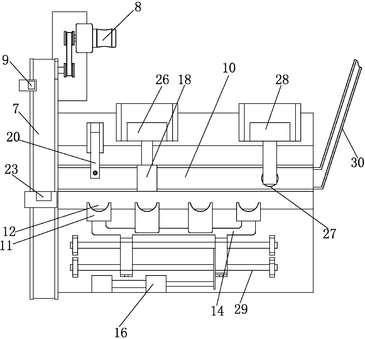
[0022] Example: such as Figure 1~4 As shown, a tapered roller bearing automatic feeding surface recognition machine of the present invention includes a feeding device 1 and a surface recognition system 2. The feeding device 1 includes a circular feeding turntable 3 inclined with respect to a horizontal plane. The angle between the disc surface of the feeding turntable 3 and the horizontal plane is 20-30 degrees. The circular feeding turntable 3 is connected with a turntable driving device that drives it to rotate. The turntable driving device is the prior art, and is along the periphery of the circular feeding turntable 3. There is a circle of baffle 4, and a feeding trough 5 is provided at the bottom end of the surface of the circular feeding turntable 3. One end of the feeding trough 5 is in the turntable, and the other end passes through the baffle 4. Before work, pour the bearing into Inside the circular feeding turntable 3, the circular feeding turntable 3 continuously ro...


PUM


Abstract

The invention discloses a conical roller bearing automatic feed and face recognizing machine. The conical roller bearing automatic feed and face recognizing machine comprises a feed device and a face recognizing system. The feed device comprises a circular feed rotary plate which is obliquely disposed relative to the horizontal face. A feed groove is formed at the bottommost end of the plate face of the circular feed rotary plate. The circular feed rotary plate continuously rotates to feed bearings into the feed groove. A guide groove is formed below the feed groove. A movable conveying belt is disposed below the guide groove. The face recognizing system comprises a face recognizing workbench, a pushing device, a recognizing device and face turning device, wherein the pushing device is used for pushing the bearing on the conveying belt into the face recognizing workbench and continuously pushing the same to move forwards, the recognizing device is used for recognizing the size of the upper end faces of the bearings, and the face turning device is used for turning the bearings into required states. The conical roller bearing automatic feed and face recognizing machine has the advantages that automatic feed and detection can be achieved, when the placing states of the bearings do not accord to preset states, the bearings can be turned automatically, state consistency of the bearings before grinding can be guaranteed, and automatic face reorganization is achieved.

Description

Technical field [0001] The invention relates to a device for regulating the placement state of tapered roller bearings before grinding raceways, in particular to an automatic feeding surface recognition machine for tapered roller bearings. Background technique [0002] The main feature of tapered roller bearings is that their inner and outer rings are both tapered raceways, which are mainly subjected to radial and axial combined loads. At present, tapered roller bearings are widely used in automobiles, rolling mills, mining, and metallurgy. , Plastic machinery and other industries. Because the inner and outer rings of the tapered roller bearing are tapered raceways, the area of ​​the front and back of the tapered roller bearing is different. It can also be said that the diameters of the two ends of the inner hole of the tapered roller bearing are different. When the tapered roller bearing grinds the raceway, it is impossible to guarantee that the faces of all products are kept u...

Claims


Application Information

Patent Timeline
IPC IPC(8): B65G47/252
Inventor 俞建东卢利军
Owner 慈溪市伊纳轴承有限公司
Learn More