Geometric correction method, device and system for projection image
A technology for geometric correction and image projection, applied in the field of image processing, can solve problems such as large correction error, inability to widely use various types of projection screens, and imperfect splicing and fusion of images, to ensure efficiency and accuracy, convenient debugging, The effect of precise goal orientation
- Summary
- Abstract
- Description
- Claims
- Application Information
AI Technical Summary
Problems solved by technology
Method used
Image
Examples
Embodiment 1
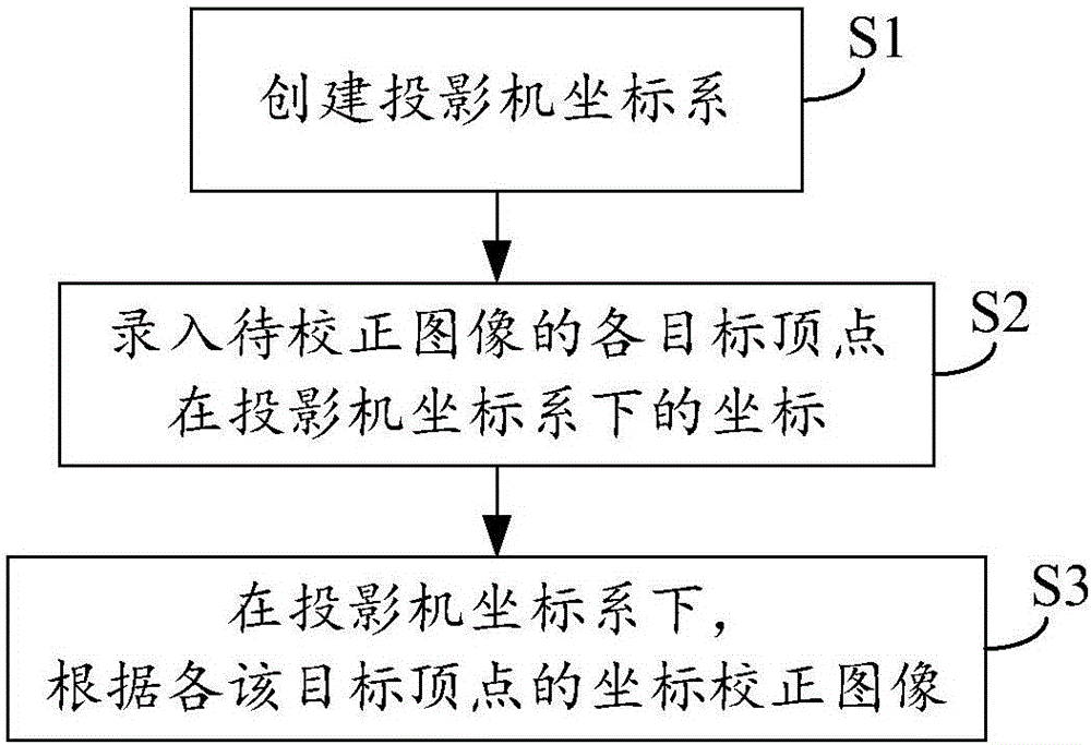
[0034] This embodiment discloses a geometric correction method of projected images. The correction of the projected image of a single projector is taken as an example to describe in detail below.
[0035] like figure 1 As shown, the method mainly includes:
[0036] Step S1, creating a projector coordinate system.
[0037] In the present invention, the "projector coordinate system" can be regarded as, but cannot be equated with, the coordinate system of the internal processing data of the projector. The so-called "coordinate system that can be regarded as the coordinate system for processing data inside the projector" refers to the regularity of the coordinate system, that is, the "projector coordinate system" is a regular coordinate system that will not change due to the shape of the projection screen. The so-called "coordinate system that is not equivalent to the internal processing data of the projector" refers to the specific execution subject that uses this coordinate s...
example 1
[0044] Example 1: Assume that the rectangular source image ABCD (A, B, C, and D are the four vertices of the rectangle) is not corrected and the area projected onto the projection screen is an irregular image, and the vertices ABCD correspond to EFGH on the screen. If the user It is necessary to select a regular rectangular area IJKL in the EFGH projection screen area as the target projection area, where I, J, K, and L are the four vertices of the target projection area, and the I vertex on the projection screen can be calibrated respectively through this test point The coordinates of vertex W in the corresponding projector coordinate system, the coordinates of vertex X in the projector coordinate system corresponding to vertex J on the projection screen, the coordinates of vertex Y in the projector coordinate system corresponding to vertex K on the projection screen, L on the projection screen The coordinates of the vertex Z in the coordinate system of the projector correspond...
Embodiment 2
[0052] This embodiment can be regarded as a special case of Embodiment 1, or:
[0053] If the first embodiment is regarded as the first correction, this embodiment can also be regarded as the second correction based on the first embodiment.
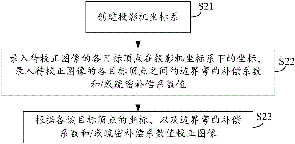
[0054] In the above-mentioned first embodiment, as described in step S3 "correcting the image according to the coordinates of each target vertex", it can perform geometric correction of the projected image according to the default boundary bending attribute between each target vertex. In this embodiment, the boundary curvature attribute can be further opened to the user, allowing them to adjust the boundary curvature attribute value of the target image through the boundary curvature compensation coefficient, and then finally correct the regular display on the projection screen through the reasonable assignment of the boundary curvature compensation coefficient projected image. Based on the same purpose, this embodiment also provides a me...
PUM
 Abstract
Description
Claims
Application Information
 - Generate Ideas
- Intellectual Property
- Life Sciences
- Materials
- Tech Scout
- Unparalleled Data Quality
- Higher Quality Content
- 60% Fewer Hallucinations
Browse by: Latest US Patents, China's latest patents, Technical Efficacy Thesaurus, Application Domain, Technology Topic, Popular Technical Reports.
© 2025 PatSnap. All rights reserved.Legal|Privacy policy|Modern Slavery Act Transparency Statement|Sitemap|About US| Contact US: help@patsnap.com


