
Wave filter bandwidth calibrating circuit

A technology of filter bandwidth and calibration circuit, applied in the direction of electrical components, output stability, etc., can solve the problem of bandwidth adjustment freedom waste and other problems, and achieve the effect of saving area, increasing degrees of freedom, and reducing design complexity

Inactive Publication Date: 2014-04-09
NAT UNIV OF DEFENSE TECH +1
View PDF4 Cites 6 Cited by
  • Summary
  • Abstract
  • Description
  • Claims
  • Application Information

AI Technical Summary

Problems solved by technology

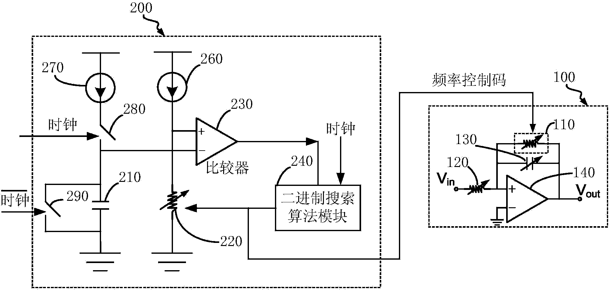
[0006] like figure 1 As shown, the existing bandwidth calibration circuit is only used to compensate the deviation of the filter bandwidth caused by the process deviation and the change of the ambient temperature. Only one of them can be used to adjust the bandwidth of the filter, while the other must be used to calibrate the bandwidth deviation. This bandwidth calibration circuit directly leads to a waste of freedom in bandwidth adjustment. For low-order filters or bandwidth frequency points For fewer filters, this method is undoubtedly acceptable, but for high-order filters that require wide-range tuning, the existing bandwidth calibration circuit will inevitably bring area and complexity to the filter This is because every time a bandwidth frequency point is increased in the design of the filter, a corresponding capacitor or resistor element must be added to each capacitor or resistor network

Method used


Image

  • Wave filter bandwidth calibrating circuit
  • Wave filter bandwidth calibrating circuit
  • Wave filter bandwidth calibrating circuit

Examples


Embodiment Construction

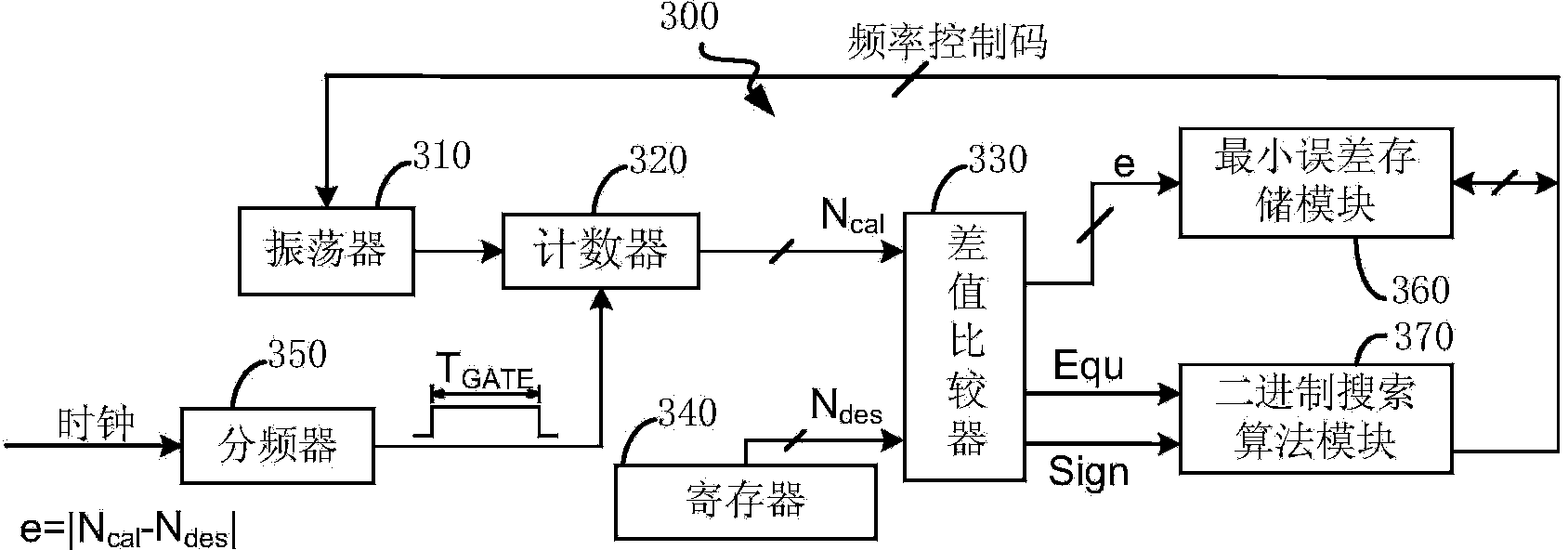
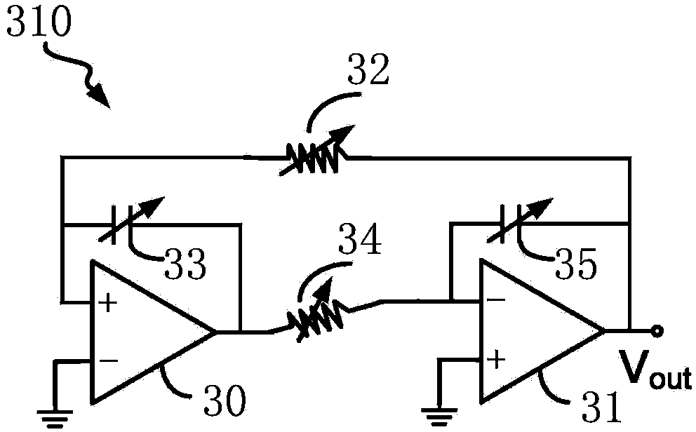
[0015] Please refer to figure 2 , which shows the structural schematic diagram of the bandwidth calibration circuit 300 of the present invention, including an oscillator 310, a counter 320, a difference comparator 330, a register 340, a frequency divider 350, a minimum error storage module 360 ​​and A binary search algorithm module 370 . The minimum error storage module 360 ​​is realized by registers and corresponding control circuits. After the bandwidth calibration circuit 300 is powered on, the binary search algorithm module 370 outputs an all-zero bit frequency control code, and controls the oscillator 310 to output a corresponding oscillation frequency (this frequency is related to the value of the capacitor array or resistor array inside the oscillator 310, It is controlled by the frequency control code, and has the same structure as the capacitor array and resistor array in the filter, see below for the specific embodiment of the oscillator), and then sent to the coun...


PUM


Abstract

The invention provides a wave filter bandwidth calibrating circuit. According to the technical scheme, the wave filter bandwidth calibrating circuit comprises an oscillator, a counter, a differential comparator, a register, a frequency divider, a minimum error storage module and a binary search algorithm module, wherein the binary search algorithm module is used for generating a frequency control code and outputting the frequency control code into the oscillator and the minimum error storage module; the oscillator is used for generating a corresponding oscillation signal and outputting the oscillation signal into the counter; the minimum error storage module is used for storing the frequency control code; the counter is used for mounting the numbers of rising edges of the oscillation signal generated by the oscillator and outputting a counting result into the differential comparator; the differential comparator is used for outputting an error absolute value obtained in a comparison mode into the minimum error storage module and outputting an error symbol into the binary search algorithm module; the minimum error storage module is used for storing the error absolute value. Compared with a wave filter designed by an existing wave filter bandwidth calibrating circuit, as the wave filter bandwidth calibrating circuit provided by the invention is used, the numbers of capacitors or resistors required by the wave filter are greatly decreased, the area is saved and the design complexity is reduced.

Description

technical field [0001] The invention relates to the field of radio frequency integrated circuits, in particular to a bandwidth calibration circuit capable of enabling the filter to have a wide continuously adjustable bandwidth range and high bandwidth frequency accuracy with a smaller area and lower complexity. Background technique [0002] In broadband communication systems, especially in multi-standard compatible communication systems, a filter with a wide adjustable bandwidth range is a very critical module. Appropriate bandwidth can effectively filter out-of-band interference and noise, and improve signal-to-noise At the same time, it will also significantly improve the out-of-band linear performance of the post-stage programmable gain amplifier and improve the linearity of the system. A high filter bandwidth will deteriorate the noise performance of the system, and even deteriorate the linear performance; a low filter bandwidth will filter out some useful signals and in...

Claims


Application Information

Patent Timeline
IPC IPC(8): H03L1/00
Inventor 李建成李松亭谷晓忱王宏义颜盾黄冲
Owner NAT UNIV OF DEFENSE TECH
Learn More