Maglev weft insertion automatic loom

A loom and weft insertion technology, applied in looms, textiles, textiles and papermaking, etc., can solve the problems of complex shuttle changing mechanism, labor-intensive, and high consumption of machine materials, shortening the process flow and speeding up the shuttle changing. , the effect of simple structure

Inactive Publication Date: 2016-07-13
高密市三佳纺织有限公司
View PDF11 Cites 0 Cited by
  • Summary
  • Abstract
  • Description
  • Claims
  • Application Information

AI Technical Summary

Problems solved by technology

[0003] Aiming at the deficiencies in the prior art, the present invention provides an automatic loom for magnetic levitation weft insertion, which solves the problem of the complexity of the shuttle changing mechanism of the traditional automatic loom, which is prone to failure, long process flow, labor intensive, machine material consumption and noise. big problem

Method used


Image

  • Maglev weft insertion automatic loom
  • Maglev weft insertion automatic loom
  • Maglev weft insertion automatic loom

Examples


Embodiment approach 1

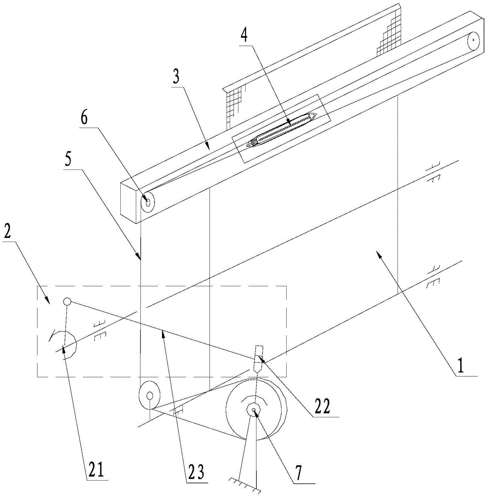
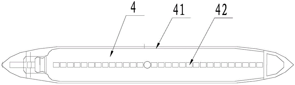
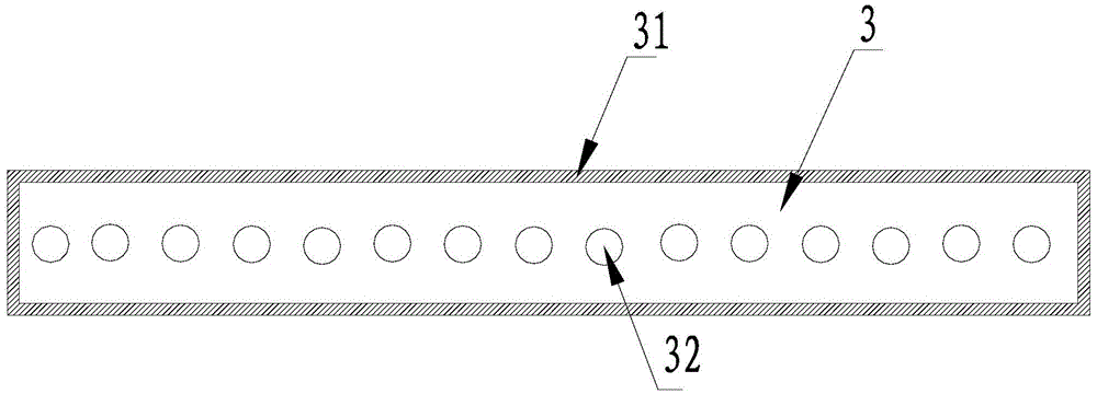
[0022] The embodiment of the present invention relates to a magnetic levitation weft insertion automatic loom, which includes a frame 1, a guide rail 3, a crank rocker mechanism 2 and a weft insertion shuttle 4, wherein the crank rocker mechanism 2 includes a rocker 21, a crank 22 and a The connecting rod 23 between the rod 21 and the crank 22, the crank rocker mechanism 2 is fixedly connected with the frame 1 by the crank 22, and the crank rocker mechanism 2 is connected with the weft insertion shuttle 4 by the weft insertion wire rope 5. In the present invention, The guide rail 3 includes a large gantry frame 31 and a guide rail magnetic sheet 32 ​​fixed on the large gantry frame 31. The weft insertion shuttle 4 includes a shuttle guide sheet 41 and a shuttle guide magnetic sheet 42. The shuttle guide magnetic sheet 42 is fixed on the bottom of the shuttle guide sheet 41. , the present invention adopts the principle of magnetic levitation, so the polarity of the opposite surf...


PUM


Abstract

The invention provides a magnetic levitation weft insertion automatic weaving loom to solve the problems that a traditional automatic weaving loom is complex in shuttle changing mechanism, prone to failures, long in process flow, high in amount of consumed labor, high in quantity of materials consumed by a machine and high in noise. The magnetic levitation weft insertion automatic weaving loom comprises a machine frame, a crank and rocker mechanism located on one side of the machine frame, a guide rail located on the machine frame, and a weft insertion shuttle located on the guide rail. The guide rail is fixed to the upper end of the machine frame. The weft insertion shuttle is connected with the crank and rocker mechanism through a weft insertion steel wire rope. The guide rail comprises a large portal frame and a guide rail magnetic sheet located on the large portal frame. The weft insertion shuttle comprises a shuttle guiding piece and a shuttle guiding magnetic sheet located at the bottom of the shuttle guiding piece. The opposite faces of the shuttle guiding magnetic sheet and the guide rail magnetic sheet have the same polarity. A steering pulley is arranged at the upper end of the machine frame. A speed increasing gear is arranged between the crank and rocker mechanism and the machine frame. The crank and rocker mechanism comprises a rocker, a crank and a connecting rod which is connected with the rocker and the crank, wherein the crank is fixed to the machine frame.

Description

technical field [0001] The invention relates to an automatic loom, in particular to a magnetic levitation weft insertion automatic loom, which belongs to the field of loom equipment. Background technique [0002] In the prior art, the shuttle change of the automatic loom is mechanical. Due to the friction, the speed of the shuttle change is slow when working, and there are strict requirements on the thickness and width of the textile during the weaving operation. When the fabric is too thick, too heavy, or the width does not meet the requirements, it will affect the speed of changing the shuttle, and even cause machine failure, which affects the speed of spinning, and requires a special person to maintain it, wasting manpower, material resources and time. There is friction, so loud noise is generated, causing noise pollution. Contents of the invention [0003] Aiming at the deficiencies in the prior art, the present invention provides an automatic loom for magnetic levita...

Claims


Application Information

Patent Timeline
Patent Type & Authority Patents(China)
IPC IPC(8): D03D45/34D03J5/02
Inventor 逄宗福杨文水
Owner 高密市三佳纺织有限公司
Why Eureka
Try Eureka