
Transmission line malfunction monitoring auxiliary device

A technology of fault monitoring and auxiliary devices, which is applied in the direction of measuring devices, fault locations, and parts of electrical measuring instruments, etc., and can solve problems such as long time for fault judgment and poor working reliability

Inactive Publication Date: 2014-04-02
AEROSPACE SCI & IND SHENZHEN GROUP
View PDF5 Cites 2 Cited by
  • Summary
  • Abstract
  • Description
  • Claims
  • Application Information

AI Technical Summary

Problems solved by technology

[0004] The present invention aims to solve the technical problems of long fault judgment time and poor work reliability of the transmission line fault monitoring device in the prior art, and provides an intuitive, fast and accurate judgment condition for the fault location, which can quickly restore the power supply in the non-fault area Transmission line fault monitoring auxiliary device

Method used


Image

  • Transmission line malfunction monitoring auxiliary device
  • Transmission line malfunction monitoring auxiliary device

Examples


Embodiment Construction

[0029] In order to make the technical problems, technical solutions and beneficial effects solved by the present invention clearer, the present invention will be further described in detail below in conjunction with the accompanying drawings and embodiments. It should be understood that the specific embodiments described here are only used to explain the present invention, not to limit the present invention.

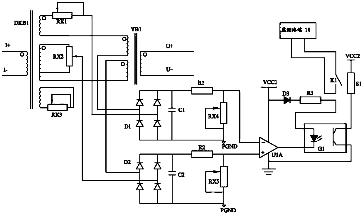
[0030] like figure 1 As shown, the embodiment of the present invention provides an auxiliary device for fault monitoring of transmission lines, which includes an electrical signal acquisition circuit 20 , a phase changing circuit 30 , an AC / DC conversion circuit 40 and a comparison output circuit 50 electrically connected in sequence.

[0031] The electrical signal acquisition circuit 20 is used to acquire the secondary phase current Ia and the secondary line voltage Ubc or the secondary phase current Ib and the secondary line voltage Uca or the secondary phase current I...


PUM


Abstract

The invention discloses a transmission line malfunction monitoring auxiliary device, comprising an electrical signal acquisition circuit, a phase conversion circuit, an alternating-direct current conversion circuit and a comparison output circuit which are electrically connected in sequence, wherein the electrical signal acquisition circuit is used for collecting a secondary phase current and a secondary phase voltage; the phase conversion circuit is used for performing phase conversion on the collected secondary phase current to obtain a first voltage vector U after phase conversion, and performing reduction voltage on the collected corresponding secondary phase voltage to obtain a second voltage vector U' after reduction voltage; the alternating-direct current conversion circuit is used for performing rectification on a vector U+U' and a vector U-U' to respectively obtain a first direct current voltage U2 and a second direct current voltage U3; the comparison output circuit is used for comparing the first direct current voltage U2 and the second direct current voltage U3, and outputting an electric signal to an external monitoring terminal according to a comparative result. On basis of the original protection device, according to the scheme, the time for recovering the power supply of regions without malfunction is effectively shortened, and the malfunction scope is effectively shrunk.

Description

technical field [0001] The invention relates to the field of electric power monitoring, in particular to an auxiliary device for fault monitoring of transmission lines. Background technique [0002] At present, the existing transmission line fault monitoring devices all have a relay protection device. The working principle of the relay protection device is basically based on the magnitude of the monitored current or voltage to judge and provide protection. When a short-circuit fault occurs, it will perform quick-break protection or time-limited protection. Or timing protection, according to the size of the current, the switch is controlled in different periods to achieve the purpose of isolating the fault and restoring power supply, or using the reclosing method to judge the voltage. Generally, the fault area can be judged and the fault area is isolated and Restoration of power to non-faulty areas. [0003] The defect of the existing relay protection device is that the curr...

Claims


Application Information

Patent Timeline
Patent Type & Authority Applications(China)
IPC IPC(8): G01R31/08G01R19/165G01R1/30
Inventor 胡忠伟
Owner AEROSPACE SCI & IND SHENZHEN GROUP
Learn More