
Structure and method for hanging and installing bottom suspension device of high speed motor train unit

A technology for high-speed EMUs and off-board equipment, which is applied in transformer/reactor installation/support/suspension, locomotives, transportation and packaging, etc. It can solve problems such as long reloading time, reduced comfort, and high transformation costs, and achieves installation The structure is simple and convenient, the effect of improving the replacement efficiency and high economic value

Active Publication Date: 2014-04-02
CRRC QINGDAO SIFANG CO LTD
View PDF6 Cites 16 Cited by
  • Summary
  • Abstract
  • Description
  • Claims
  • Application Information

AI Technical Summary

Problems solved by technology

Due to the rigid connection and the heavy weight of the traction transformer, the hysteresis vibration of the traction transformer will cause excessive vibration and noise in the passenger compartment of the vehicle, and the comfort level will be significantly reduced
[0003] If the above-mentioned traction transformer and the car body are converted from a rigid connection to an elastic connection, the existing car body needs to be modified, which has high technical risks, or the car body is scrapped and redesigned, which will take a long time and cost a lot.
[0004] In addition, the elastic suspension of traction transformers of other EMUs in China usually adopts four suspension points, both the upper elastic suspension and the lower suspension installation, but when replacing the shock absorber, the transformer needs to be disassembled to replace it. , and requires special requirements such as workbench, changing tooling, and multiple personnel, and the changing time is long

Method used


Image

  • Structure and method for hanging and installing bottom suspension device of high speed motor train unit
  • Structure and method for hanging and installing bottom suspension device of high speed motor train unit
  • Structure and method for hanging and installing bottom suspension device of high speed motor train unit

Examples


Embodiment Construction

[0034] Below in conjunction with accompanying drawing and specific embodiment the present invention is described in further detail:

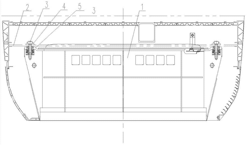
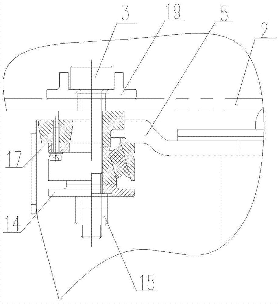
[0035] like Figure 2 to Figure 4 As shown, the present invention provides a hanging installation structure for the undercarriage equipment of a high-speed EMU. In this embodiment, the traction transformer 1 is used as an example for the undercarriage equipment to be described in detail.

[0036] The traction transformer 1 is suspended below the crossbeam 2 of the underframe of the car body, and the mounting part 4 is arranged on the crossbeam 2 of the underframe of the carbody, and the mounting seat 5 is correspondingly arranged on the traction transformer 1. On both sides of the top of the traction transformer 1, There is one mounting seat 5, and eight mounting holes 6 are provided on each mounting seat 5. Correspondingly, two mounting parts 4 for hanging the traction transformer 1 are provided on the vehicle body underframe beam 2, and each ...


PUM


Abstract

The invention relates to a structure and a method for hanging and installing a bottom suspension device of a high speed motor train unit. The bottom suspension device is hung on a crossbeam of a train body undercarriage, the crossbeam of the train body undercarriage is provided with an installation part, the bottom suspension device is correspondently provided with an installation seat, the installation part is provided with a suspension hole, the installation seat is provided with an installation hole, a suspension bolt sequentially penetrates through the suspension hole in the crossbeam of the train body undercarriage and the installation hole in the bottom suspension device from top to bottom, a gasket and a shock absorber are sequentially arranged in the installation holes in a penetrating manner, the gasket and the shock absorber are sleeved on the suspension bolt, the shock absorber is fixedly connected with the installation seat, a protection supporting plate is also sleeved on the bottom of the shock absorber, and the bottom of the protection supporting plate is fixed in a locking manner through a tightening nut. By adopting the structure and the method, under the situation that the original light-weight train body structure is not changed, the installation of the bottom suspension device can be modified, the modification cost is low, the period is short, and the structure and the method are suitable for modifying the train from a multi-point rigid connection to the resilient structure.

Description

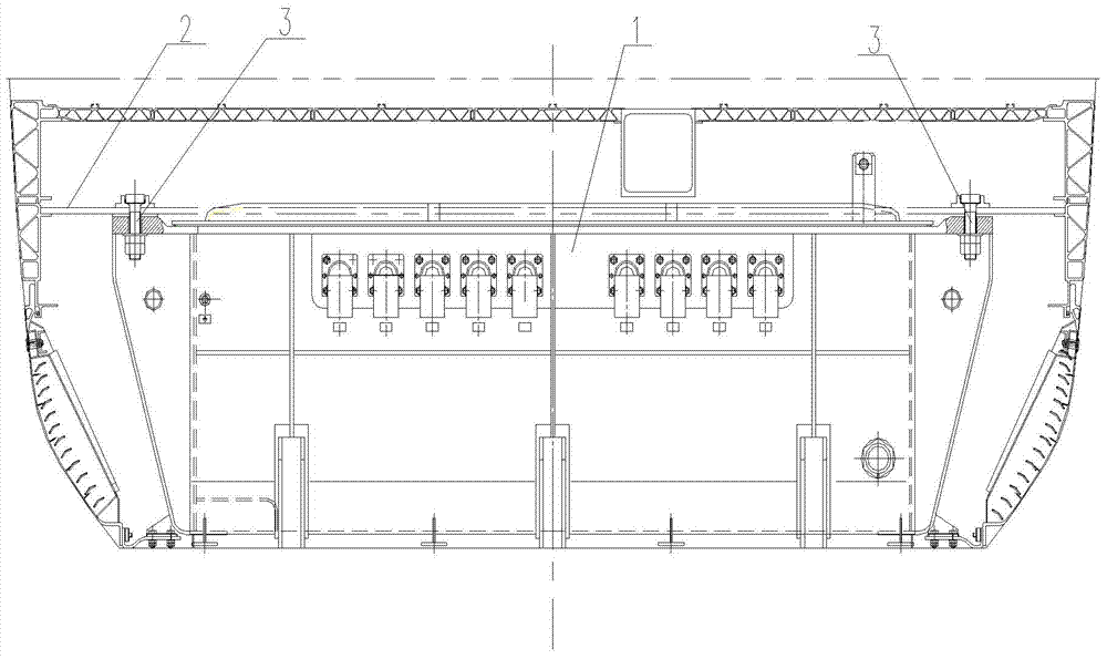
technical field [0001] The present invention relates to an installation structure and installation method of high-speed EMU undercarriage equipment, in particular to an undercarriage traction transformer and other extra-heavy undercarriage equipment with a vibration source, which is suspended and installed on a lightweight car body. Installation structure and installation method. Background technique [0002] There are many off-board equipment installed under the high-speed EMU, such as traction transformers, traction converters, off-board air-conditioning units, dirt tanks, water tanks, braking equipment, etc., among which the weight of traction transformers and traction converters is heavier. On previous EMUs, such as figure 1 As shown, the traction transformer 1 and other equipment are rigidly connected to the vehicle body underframe beam 2 through 16 suspension points, and the traction transformer 1 and the vehicle body underframe beam 2 are fixedly connected by suspen...

Claims


Application Information

Patent Timeline
IPC IPC(8): B61F1/08B61C17/00H01F27/06
Inventor 单永林李宏王军龚明马云双宋红房楠
Owner CRRC QINGDAO SIFANG CO LTD
Learn More