Magnetic force assisted die locking die-clamping unit of energy-saving type injection molding machine

A mold clamping mechanism and injection molding machine technology, applied in the field of mold clamping mechanisms, can solve the problems of low working efficiency and complex structure of the electromagnetic clamping mechanism, and achieve the effects of overcoming the shortcomings of oil unloading, high working efficiency, and preventing inertial impact.

Active Publication Date: 2014-04-02
ZHEJIANG UNIV +1
View PDF11 Cites 1 Cited by
  • Summary
  • Abstract
  • Description
  • Claims
  • Application Information

AI Technical Summary

Problems solved by technology

[0008] In order to overcome the shortcomings of the three-platen double toggle mold clamping mechanism and the two-platen direct pressure mold clamping mechanism in the background technology of unloading oil, as well as the low working efficiency and complex structure of the electromagnetic mold clamping mechanism, the purpose of the present invention is to provide a magnetic assisted mold clamping Energy-saving injection molding machine clamping mechanism

Method used


Image

  • Magnetic force assisted die locking die-clamping unit of energy-saving type injection molding machine
  • Magnetic force assisted die locking die-clamping unit of energy-saving type injection molding machine
  • Magnetic force assisted die locking die-clamping unit of energy-saving type injection molding machine

Examples


Embodiment Construction

[0019] The present invention will be further described below in conjunction with the accompanying drawings and specific embodiments.

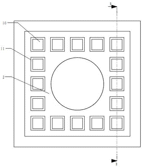
[0020] Such as figure 1 , figure 2 As shown, the present invention includes a fixed template 1, a movable template 4, four pull rods 3 and a mold clamping cylinder 5, and after the four pull rods 3 pass through the respective positioning holes of the movable template 4 and the fixed template 1 in turn, one end of the four pull rods 3 is connected to the fixed template 1. The fixed template 1 is fixed, and the fixed template 1 is vertically fixed on the base of the injection molding machine. The other ends of the four tie rods 3 form a sliding fit with the movable template 4. The four tie rods 3 are fixed on the base of the injection molding machine and are located inside the four tie rods. There is a fixed template groove 8 in the center of the fixed template, and a clamping mold half 6 is housed in the fixed template groove 8, and a movable ...


PUM


Abstract

The invention discloses a magnetic force assisted die locking die-clamping unit of an energy-saving type injection molding machine. After four pull rods of the of the magnetic force assisted die locking die-clamping unit orderly penetrate through the respective positioning holes of a movable template and a fixed template orderly, one ends of the four pull rods are fixedly connected with the fixed template and the other ends of the four pull rods are in sliding fit with the movable template; a die-clamping semi-die is mounted in a fixed template groove in the center of the fixed template in the four pull rods, while another die-clamping semi-die is mounted in the movable template groove in the center of the movable template; the center of the outer side of the movable template is connected with a connecting rod of a die-clamping cylinder. The die-clamping unit further comprises eight magnetic polar plates with the same structure; the eight magnetic polar plates are mounted at the inner joints between the corresponding pull rods and the fixed template, respectively, while the other four magnetic polar plates are mounted at the inner joints between the corresponding pull rods and the movable template, respectively. Coils wound on iron cores in the magnetic polar plates are electrified to generate a magnetic force so that the fixed template and the movable template are tensioned and the die locking force is enhanced. The fixed template of the die-clamping unit is capable of attracting the movable template through the magnetic force; the die locking force is increased and stabilized; the magnetic force assisted die locking die-clamping unit of the energy-saving type injection molding machine is simple in structure and high in working efficiency.

Description

technical field [0001] The invention relates to a mold clamping mechanism, in particular to an energy-saving mold clamping mechanism for an injection molding machine with magnetic force assisted mold clamping. Background technique [0002] The mold clamping mechanism is one of the key components of the injection molding machine. Its function is to realize the opening and closing movement of the mold. It is the elastic deformation of the mold closing system to achieve the clamping force and lock the mold. [0003] At present, the main ways to provide the clamping force of the mold clamping mechanism of the injection molding machine are to use the hydraulic cylinder to generate force to lock, and to use the servo motor to drive the screw to generate pressure to lock. [0004] At present, the mold clamping mechanism of domestic injection molding machines is the most commonly used five-point double toggle mold clamping mechanism. Although it has the function of force amplificati...

Claims


Application Information

Patent Timeline
Patent Type & Authority Applications(China)
IPC IPC(8): B29C45/64
CPCB29C45/67B29C2045/645
Inventor 张树有朱俏俏
Owner ZHEJIANG UNIV
Why Eureka
Try Eureka