Spinning machine with compactor

A spinning machine, compaction unit technology, applied in the spinning machine, continuous winding spinning machine, textile and papermaking, etc., can solve the problem of not being aligned with each other accurately, and achieve the effect of fast operability

Active Publication Date: 2017-05-24
MASCHINENFABRIK RIETER AG
View PDF8 Cites 0 Cited by
  • Summary
  • Abstract
  • Description
  • Claims
  • Application Information

AI Technical Summary

Problems solved by technology

Furthermore, with this solution, there is no direct mutually coordinated positioning of the deflectable pressure rods of the pressure rollers of the drafting unit and the deflectable compaction unit, which sometimes, for example, Can have a detrimental effect if the individual rollers are not aligned precisely with each other

Method used


Image

  • Spinning machine with compactor
  • Spinning machine with compactor
  • Spinning machine with compactor

Examples


Embodiment Construction

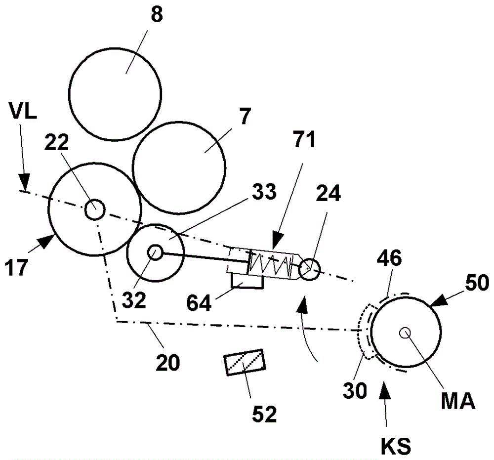
[0035] figure 1 Shows a schematic side view of a spinning position 1 of a spinning machine (ring spinning frame) with drafting unit 2 provided with input roller pairs 3, 4, intermediate rollers Pair 5, 6 and output roller pair 7, 8. A belt 12 , 13 is each guided around the intermediate roller pair 5 , 6 , and is held in its position shown in each case around a cage (not shown in detail). The upper rollers 4 , 6 , 8 of the roller pairs mentioned are designed as pressure rollers, which are mounted rotatably via shafts on pivotally mounted pressure rods 10 . The pressure rod 10 is mounted so as to be pivotable about an axis 15 , which is acted upon by a spring element F as schematically shown. This spring element can also be an air hose, for example. By means of the schematically indicated spring loading, the rollers 4, 6, 8 are pressed against the lower rollers 3, 5 and 7 of the roller pair in order to form a clamp for the spinning material bit. The roller pairs 3 , 5 , 7 a...


PUM


Abstract

The invention relates to a device for compacting fiber strands (V) on a spinning machine, comprising a pair of drafting rollers (3, 4; 5, 6; 7, 8) The drafting mechanism unit (2), the pressure rollers (4, 6, 8) of the drafting mechanism roller pair are held on the pressure rod (10) supported on the frame (MR) in a deflectable manner and has a compacting unit (VM) deflectably mounted on the frame (MR) immediately behind the output roller pair (7, 8) of the drafting mechanism unit (2) , the deflection axis (MA) of the compacting unit extends parallel to and spaced relative to the axis of rotation (7a, 8a) of the output roller pair (7, 8), and the compacting unit has a carriage ( 20), at least one suction drum (17) provided with a suction zone (Z) is rotatably supported on said carriage, in order to form a clamping line (P) at the end of said suction zone (Z) , correspondingly a pinch roller (33) fixed on the bracket (20) is placed on the suction drum under the action of the pressure element (F2), and in order to move the output roller pair (7, 8) forming a drive connection between the lower roller (7) and said suction drum (17) via at least one spring element (F1 , 55; 68) load the carriage (20), thereby moving the suction drum (17) towards the lower roller (7) of the output roller pair (7, 8). In order to improve the known solutions, it is proposed to provide guides (30) in the region of the deflection axis (MA) of the carrier (20) of the compaction unit (VM), by means of which the The compaction unit is fixed in the position where it is mounted on the frame (MR), seen in the direction of its deflection axis (MA), and the spring element (F1, 55; 68) is mounted on the compactor on the free end of the rod (10).

Description

technical field [0001] The invention relates to a device for compacting fiber strands on a spinning machine. Background technique [0002] Numerous embodiments are known from practice in which a compacting device is arranged downstream for the compacting (compacting) of the spinning material (fiber sliver) delivered by the drafting unit. Immediately after such a compacting device, the compacted spinning material is fed to the twist generating device after passing through the clamping station. Such a twist generating device is formed, for example in the case of ring spinning machines, by a traveler which rotates on a ring, wherein the yarn produced is wound onto a rotating bobbin. As a compacting device, mainly the mentioned rotating perforated suction drums or rotating perforated belts are used. [0003] In this case, compacting devices are known which can also be retrofitted later on to the existing drafting unit. [0004] Such a compacting device is known, for example, ...

Claims


Application Information

Patent Timeline
Patent Type & Authority Patents(China)
IPC IPC(8): D01H5/70D01H5/72D01H1/02
CPCD01H1/025D01H5/72D01H5/74D01H5/86
Inventor G.施内德L.马里纳R.内格里
Owner MASCHINENFABRIK RIETER AG
Why Eureka
Try Eureka