
Integrated servo motor

A servo motor and integrated circuit technology, applied in the field of motors, can solve the problems of poor cooling effect, inconvenient maintenance, explosion, etc., and achieve the effect of ensuring performance, good cooling effect and good heat dissipation effect.

Active Publication Date: 2014-03-26
NINGBO TENGLONG OUTDOOR IMPLEMENT
View PDF6 Cites 15 Cited by
  • Summary
  • Abstract
  • Description
  • Claims
  • Application Information

AI Technical Summary

Problems solved by technology

[0004] 1) Since both the servo driver and the servo motor are cooled by natural cooling, the cooling effect is poor; and the servo driver is installed on the radiator of the servo motor, therefore, the connection of the radiator connected to the servo driver The heat cannot be dissipated in time, resulting in poor cooling effect of the radiator;
[0005] 2) In addition, there are high-power modules installed in the servo driver, which will generate a lot of heat during operation. Therefore, the servo driver must be cooled to ensure normal operation. However, the cooling in the prior art usually only adopts natural cooling. In other words, the casing of the servo drive has air holes that communicate with the outside world, so that the electrical components in the servo drive are cooled by natural air. Therefore, on the one hand, the cooling effect of the servo drive is poor, on the other hand , the servo drive will accumulate dust and other impurities, which will affect the performance of electrical components; on the other hand, because the servo drive is connected to the outside world, the moisture in the air will also affect the use of electrical components. Potential safety hazards that can cause explosions;
[0006] 3) In addition, since the encoder is connected with the servo drive, when the servo drive is maintained or regularly inspected, the encoder must also be removed at the same time. Therefore, on the one hand, the original data of the encoder will be destroyed. On the other hand, maintenance is also very inconvenient

Method used


Image

  • Integrated servo motor
  • Integrated servo motor
  • Integrated servo motor

Examples


Embodiment Construction

[0031] The present invention will be described in further detail below in conjunction with the accompanying drawings and specific embodiments.

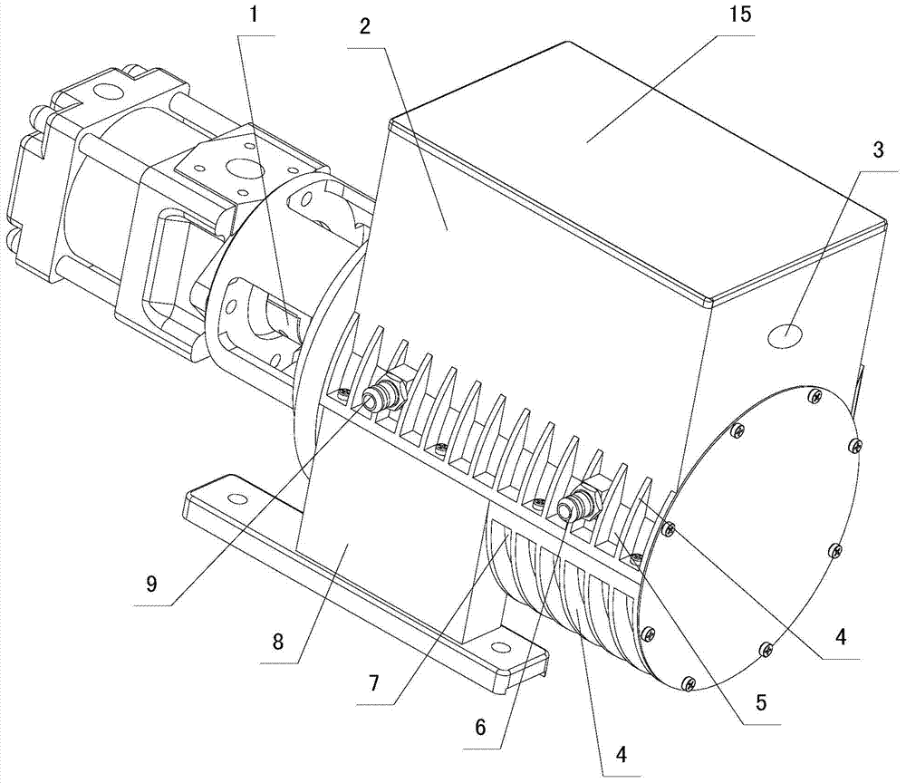
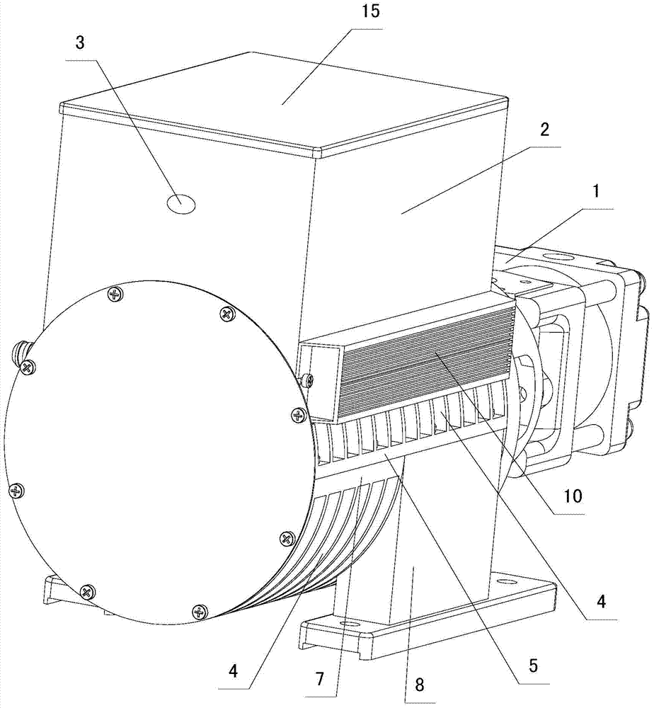
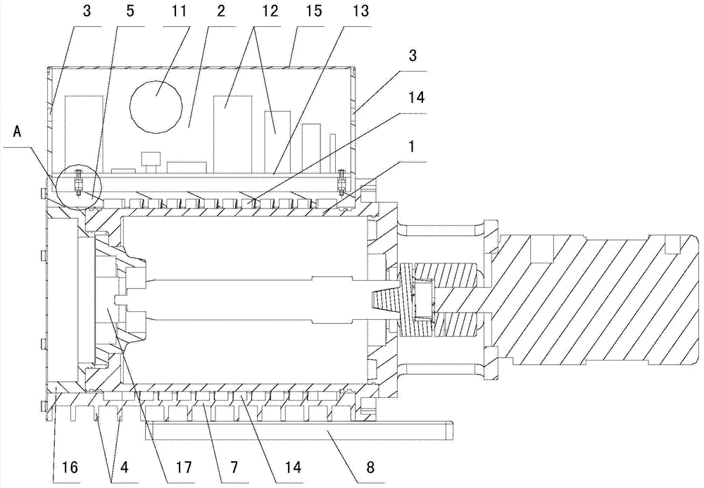
[0032] Depend on Figure 1 to Figure 4 and Figure 6 It can be seen from the schematic structural diagram of the integrated servo motor of the present invention that it includes an electrical junction box 16, an encoder 17, a connected servo motor 1 and a servo driver. The servo motor 1 is connected to the servo driver through a cooling device, the cooling device includes a cooling jacket, the servo motor 1 is sleeved in the cooling jacket, the casing 2 of the servo driver is connected to the cooling jacket, and the wall of the cooling jacket has a cooling aisle. The casing 2 of described servo drive is the casing that the inside that metal heat-conducting material is made is the casing of airtight cavity, and fan 11 is installed in it. The electrical junction box 16 is located in the cooling jacket, and the encoder 17 is connected...


PUM


Abstract

The invention discloses an integrated servo motor. A servo motor body (1) is connected with a servo driver via a cooler, the cooler comprises a cooling jacket which is sleeved on the servo motor body (1), a casing (2) of the servo driver is connected with the cooling jacket, and the wall of the cooling jacket includes cooling channels; the casing (2) of the servo driver internally includes an enclosed cavity and is made of a metal heat-conductive material, and a fan (11) is installed in the casing; an electrical conjunction box (16) is positioned in the cooling jacket, and an encoder (17) is connected with one end, close to the electrical conjunction box (16), of a central shaft of the servo motor body (1); and a vibration-proof device which is used for protecting electronic components (12) in the servo driver is arranged in the servo driver. The integrated servo motor of such structure is good in heat radiation and cooling effects, and is convenient to maintain.

Description

technical field [0001] The invention relates to the technical field of motors, in particular to an integrated servo motor integrating a servo motor and a servo driver. Background technique [0002] At present, in the technical fields such as motors and motors, the servo motor and the servo drive are independent structural units separated from each other. In practical applications, these two independent units must be connected by signal cables and power cables, and the position of the servo motor is connected by the cable. , The speed information is transmitted to the servo driver and the control signal of the servo driver is sent to the servo motor. Due to defects such as complicated cable routing and difficult maintenance, the servo motor and servo driver are usually made into an integrated structure. For example, the invention patent with the publication number CN1877970A and the name "integrated motor" disclosed on the Chinese patent website integrates the servo driver a...

Claims


Application Information

Patent Timeline
IPC IPC(8): H02K11/00H02K9/14H02K9/19H02K5/20H05K7/20H02K11/33
Inventor 刘坚
Owner NINGBO TENGLONG OUTDOOR IMPLEMENT
Learn More